|
|
|
A practical problem when measuring the capacitance of a flat capacitor with air dielectric
Date 05/26
This is a preliminary demonstrative measurement for the E-field thruster project. A flat disc capacitor has been made from cardboard and aluminum foil with air dielectric to measure its capacitance with digital multimeter and compare the measured value with the theoretical value calculated as C=e0S/d. Here e0 is the dielectric constant of the vacuum (or air); S is the surface area of one side of one electrode; d distance between the electrodes. This formula is valid only when the effect of the scattered E-field at the edges can be neglected, and the E-field considered to be everywhere homogeneous between the plates. This condition is approximately fulfilled when the distance between the electrodes is much smaller than the size of the plates. The prepared test capacitor does not fulfills this condition very well, thus we can expect that the measured real value will deviate with about 10 30% from the calculated.
The electrodes are made of cardboard covered with aluminum foil. The foil is fixed to the cardboard using adhesive tape sticking on both sides. The diameter of the electrode is 16 cm.
Two ring spacers made of cardboard 10 mm wide are glued to the surface of the electrode with universal glue.
After drying, the other electrode is glued similarly to the other side of the spacers. Thus the gap between the plates is 10 mm. The digital multimeter used is Escort EDM-83B. It is switched to the lowest range of 4 nF, where it has a resolution of 1 pF and an accuracy of +-(2 % rdg+5dgt). This accuracy is valid with film capacitor or better, according to the operators manual. When the probes are not connected to the plates, the instrument shows 146 pF residual capacitance that has been compensated by using the relative mode (see next picture).
Using the relative mode the self-capacitance of the probes and the instrument is compensated.
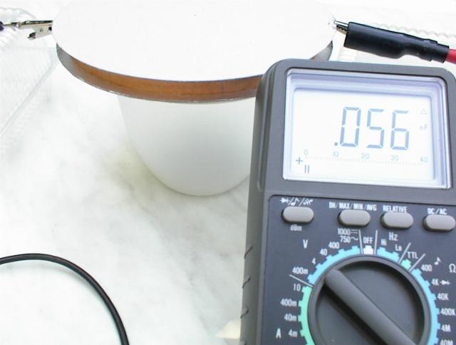
The capacitance of the condenser is measured to be 56 pF. After leaving the capacitor for an hour more to dry, and repeating the measurement the result was 45 pf.
When the expected capacitance is calculated with the formula C=8.854E-12*S/d we get: C=8.854E-12*(8E-2)^2*3.14/1E-2=17.8 pF. The measured value is 3.15 times greater than the calculated (or 2.53 times calculating with the second value).
For analog instruments it is known that the specified accuracy is valid only if the measured value is close to (or above) the 2/3 region of the scale. If this were the same for the digital instruments then it could explain the big deviation between the measured and calculated values. However according to the specification such great error can not be explained on account of the instrument. Measuring a ceramic capacitor that should be 100 pF according to the numbers written on it, the instrument showed a capacitance of 105 pF that is an excellent value when compared to the declared nominal capacitance. Naturally due to the scattered E-field at the edges of the capacitor the shown formula will not give an accurate value, ant the real value can be calculated with good accuracy only with numerical methodes. However according to the numerical analysis of Fred M. Erickson this much deviation can not be explained away on that account. The numerical analysis of the flat disc condenser's capacitance made by Fred M. Erickson (in compressed postscript format) can be downloaded from here.
Second day update (05/27)
Finally I have found the cause for the weird measurement results. The instrument is very sensitive in the lowest range of capacitance measurement (4 nF). The sensitivity here does not means only that the indicated capacitance is slightly changing when your hands or body comes too close to the measured object and test-leads, but it is specially sensitive for the leakage current through the capacitor. The resistance of the home-made capacitor has been measured and it was about 250 Mohm. This is a fairly big value but it has still falsified the measurement result in a rough manner.
To check whether the problem is with the instrument or with the method of measurement I have selected 3 commercial ceramic condensers of low value and measured their capacitance. The condenser with a nominal value of 33 pF was measured to be of 34 pF, the other 10 pF condenser was measured to be 12 pF and the one with 16 pF sign was17 pF. This shows an excellent accuracy even for such low capacitances, thus we can be sure that the instrument and the measuring method is OK.
To verify the suspicion that an internal conductivity of the home-made capacitor might falsify the measurement results I have taken a piece of a cardboard that was colored black on one side and measured its resistance that was about 370 Mohm. Measured one commercial ceramic capacitor that showed a value of 34 pF, and then while measuring the capacitance pressed the probes (that were at the same time connected to the legs of the condenser) to the colored side of the cardboard. The instrument showed a capacitance of about 50 pF, but when decreased the resistance by shortening the distance between the probes on the cardboard, the indicated value increased above 100 pF (that supposed to be only 34 pF).
This experiment proved that the real capacitance of the condenser was falsified by the limited (relatively low) resistance of the cardboard spacer. The commercial condensers showed good results since their inner resistance was well above 4000 Mohms because my instrument could not measure it.
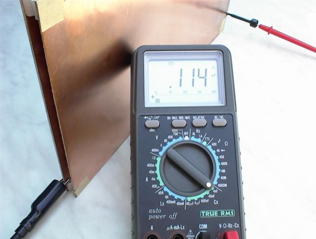
After this recognition I have measured again a previously tested square shaped home-made flat condenser, that had 4 plastic spacers and 4 adhesive tapes at the corners to keep it together. The instrument showed about 114 pF just as yesterday, although according to the calculation the expected value supposed to be between 64 and 71 pF (taking into account that the distance between the electrodes might not be exactly the same everywhere and it should be between 9 and 10 mm). After removing the adhesive tapes (those have not enough resistance) keeping only the plastic spacers, the measured value was 87 pF. This is a fairly good value since it is only 1.36 or 1,23 times more than calculated with the idealistic formula. That 36% or 23 % difference can be attributed to the edge effect, since the E-field is not homogeneous near the edges and it is predicted by the numerical analysis.
Thus we can conclude that the measurement of low capacitances are very sensitive for low resistance (leaky) dielectrics, and we should keep this in mind while designing and measuring the capacitor. In the next higher range of 40 nF the instrument is not so sensitive anymore and better accuracy can be achieved.
Created by Zoltan Losonc (feprinciples@on.mailshell.com) on 26 May 2003 and it was available for the feprinciples-group members. Last updated and published on 6 September 2003.
|
Measurement |
|