Solar pumping
Solar pumping involves using solar power/photovoltaics to power pumps for:
- pumping from a well or a pond/lake for domestic use, usually for a cottage or rural house,
- pumping from a tank to sink, shower and toilet in a recreational vehicle (RV),
- pumping from a pond to a stock trough for animal use,
- pumping from a well for irrigation,
- circulating pool water through a filter, solar pool heating tubes, ..., and
- others...
We'll illustrate some of the above examples to show possible configurations and components needed and then talk about sizing a system.
Solar pumping examples
Solar pumping for cottage/rural house
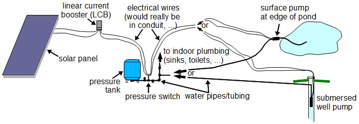
A pumping system for people often includes a pressure tank. People who install systems without pressure tanks often find that the pressure for their showers or flush toilets is not enough. A pressure tank is a storage container for water that can store the water at a large pressure without bursting. The pump in the pond or well pumps the water into this pressure tank. The force to create this pressure is really coming from the pump so in a pressure tank system, the pump is more powerful than it would be otherwise. With a pressure tank system, the water in the pipes just behind the taps, toilet, ... are also under pressure so when you open a tap you get good pressure water immediately.
A pressure tank is also intended for storage. With the tank, when you turn on a tap, most of the time there will be enough water in the tank to suit your needs and the pump won't have to turn on. This extends the life of your pump.
Notice the pressure switch in the above diagram and that the electrical wiring coming from the solar panels going to the pump is wired through it. Notice also that the pressure switch is also connected to the water pipes. This is so that it can sense the pressure in the pipes and hence the tank. If the pressure is below a user selectable amount (e.g. 40psi) then the pressure switch will connect the electrical wires, electricity can flow to the pump and the pump will start pumping water into the pressure tank. Once the pressure is sufficiently high (e.g. 60psi), the pressure switch will sense it and disconnect the electrical wires, turning off the pump.
A solar pumping system where the pump gets its power directly from the solar panels with no intermediate storage is refered to as a solar direct system. The above diagram illustrates just such a system. However, in a cottage, that same solar system is often also powering lights, a TV, ... and so would be a more complete system with charge controller, batteries and inverter. The pump would be just another load in this system, getting its power from the batteries through the inverter and would not be solar direct.
In the above diagram you can see something called a linear current booster (LCB). This increases the number of hours a day that the pump can run, adding dawn and dusk. It also allows the pump to run under cloudy conditions. If you are going with a solar direct system then you will want a LCB. It works by remixing the voltage and current supplied by the solar panels to better suit the pump motor during poor sunlight conditions. Without this remixing, the voltage a current are such that the pump motor won't run at those times.
Solar pumping to stock trough
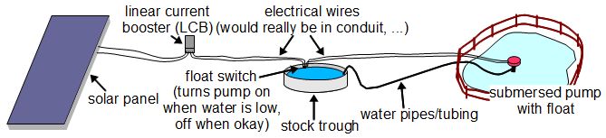
In the case of cattle, the reason for pumping from a well is obvious, cattle can't drink from a well. The reason for pumping from a pond is to keep the cattle from going near the pond and contaminating it. It's been found to be much healthier if the pond is fenced off from the cattle and the water is pumped to a cattle-accessible trough which the cattle can only drink from. The system can consist of a single solar panel to power the pump only when there is sun.
Be careful when purchasing a float switch. Make sure you get a "pump up switch". This is one where the switch is closed (pump is turned on) when the float is down and the switch is opened (pump is turned off) when the float is up. If the float switch is normally used for sump pumps then the action is the opposite.
In the above diagram, the water is pumped directly to the trough. If more storage is needed then it can first be pumped to a much larger storage tank that is located physically above the trough. Then, under the control of a float switch that mechanically opens and closes a valve, the water can be lowered into the stock trough as needed.
Sizing solar pumping systems
Final sizing of your pumping system in order to select a pump and solar panels is best done by the company or companies supplying your system. In Ottawa, ON, Canada, the this can be done by Ottawa Solar Power. A wide selection of pumps can be gotten from Mannion's Pump House, conveniently located 2 doors away from Ottawa Solar Power. If installing a well then the person putting in your well may be the first one involved. However, there are certain pieces of information that the people doing the sizing will need. The following explains that information so that you can have it ready.
Pumps are usually specified in terms of head and flow rate (also known as capacity.) Head is in turn made up of other numbers. Bring all this to the solar company who will select a pump for you. You may have to get some of the numbers from whoever is putting in your well. The solar company will take the head, flow rate and a description of what you want to achieve and select a suitable type of pump. They will then look through performance curves for various pumps to find the right one. Next they will figure out the correct solar panel configuration and talk to you about location, whether you need batteries or a direct solar system, ...
The flow rate is the amount of water you need for a given
period of time. When sizing pumps it is typically given in US gallons per minute (GPM).
For flow rate, first determine your daily water usage. This is your pump's required
flow rate per day. But your pump won't be running all day. Its limit is the number of
hours of bright sunlight you get since ultimately that's what powers the pump. So for
75 gallons per day, and assuming 3 hours per day of bright sunlight, we would get
0.417 GPM using the following formula:

Total Dynamic Head (TDH) (we'll just say head) is basically the sum of all the things that the pump will have to work against. It will have to pump water up some height. It will have to pump water through pipes that have friction and so will slow the water down. It will have to produce the required pressure for a pressure tank. And so on. Head is specified in feet. For things, such as friction, the charts you'll learn about below will give you the equivalent values in feet.
There are two formulas for head. One for if your pump will be submersed in the water and one for if it will be on the surface. Detailed descriptions for each item in formulas are below.
The following is the formula for the head when using a submersed pump:

The following is the formula for the head when using a surface pump:

Now that you know the head and the flow rate, these can be used to find a suitable pump since pumps are usually specified by these two numbers. Pumps actually operate at a range of heads and flow rates. The higher the head, the lower the flow rate and vice versa. In plain english that says the higher the pump has to pump the water, the slower the water will flow, and vice versa. The performance curve for a pump shows this relationship as well as the performance of the pump for each combination. Typically a pump is selected which has a good performance that is near the middle of the chart. The horsepower is also shown on the chart for the different combinations of head and flow rate.
Once the pump is selected, the horsepower of the pump is converted to electrical
power (in watts) using this formula:

Using the electrical power you can start to size the solar system. A simple rule of thumb is to multiply the electrical power by 1.25 to make up for inefficiencies in the system components. A solar company would work this out more precisely.
Detail descriptions for items in formulas
Vertical lift/elevation - If pumping from a well with a submersed pump then this is the vertical distance between the well head and the destination. If pumping from a pond using a pump that is submersed in the pond, then this is the vertical distance between the surface of the pond and the destination. If pumping from a well or a pond using a pump that is on the surface (e.g. on the shore in the case of a pond) then this is the vertical distance from the outlet of the pump to the destination.
Service pressure - This is the desired pressure at the destination (cottage or house). Basically it's the pressure you want to create in the pressure tank (e.g. 60psi.)
Friction loss (head loss) - As water flows through a pipe it encounters friction. Also, as the water goes around elbows, through couplings, ... it encounters friction. The pump has to provide enough pressure to make up for all that friction. The larger the pipe you use, the less friction there will be. However, the larger the pipe the less the flow too, and with too slow a flow you can have sediment buildup. So use a large enough size to keep the friction down but not too large.
Luckily friction loss charts (or head loss charts) exist that, given the pipe diameter, the flow rate (in gallons per minute (GPM)) and the pipe material (steel or plastic), will tell you how much friction you'll have for a 100 foot length. They tell you the friction in terms of head. This is so that you can easily add it to all the other things the pump has to work against in order to come up with your total dymanic head, as discussed above. Some sample friction loss charts are given below. So for example, if using a 3/4" plastic pipe and a flow rate of 6 GPM, the head will be 7.95 feet (from looking at the chart.) This means that the friction will be equivalent to pumping the water vertically 7.95 feet for every 100 feet of pipe. If we need to pump 150 feet then we multiply that by 1.5 (150 divided by 100 is 1.5) so 11.2 feet. But if you used a 1" diameter pipe instead, the head for 100 feet would be 2.45 feet or 3.67 feet for a 150 foot length of pipe.
| 3/4" pipe | ||
|---|---|---|
| Flow US GPM |
Steel C-100 |
Plastic C-140 |
| 2 | 1.93 | 1.04 |
| 3 | 4.08 | 2.21 |
| 4 | 6.94 | 3.74 |
| 5 | 10.50 | 5.66 |
| 6 | 7.95 | |
| 7 | 10.60 | |
| 1" pipe | ||
|---|---|---|
| Flow US GPM |
Steel C-100 |
Plastic C-140 |
| 2 | .595 | .322 |
| 3 | 1.25 | .680 |
| 4 | 2.14 | 1.15 |
| 5 | 3.42 | 1.75 |
| 6 | 4.54 | 2.45 |
| 7 | 6.13 | 3.30 |
Friction loss charts exist also for elbows, couplings, ...
Drawdown - If you have a submersed pump, especially in a well, then when the pump begins pumping, the water level drops. The distance that the surface of the water drops is called the drawdown. For pumping from a pond this doesn't likely amount to anything.
Pumping Level - If you have a well with a submersed pump then this is the vertical distance between the well head and the lowest that the surface of the water will drop during pumping. If pumping from a pond using a pump that is submersed in the pond then this is not a factor, i.e. 0 feet. If you have a surface pump, regardless of whether it's with a well or a pond, this is the vertical distance between the pump inlet and the lowest that the surface of the water will drop during pumping.
