Solar power on an RV (Recreational Vehicle) or motorhome
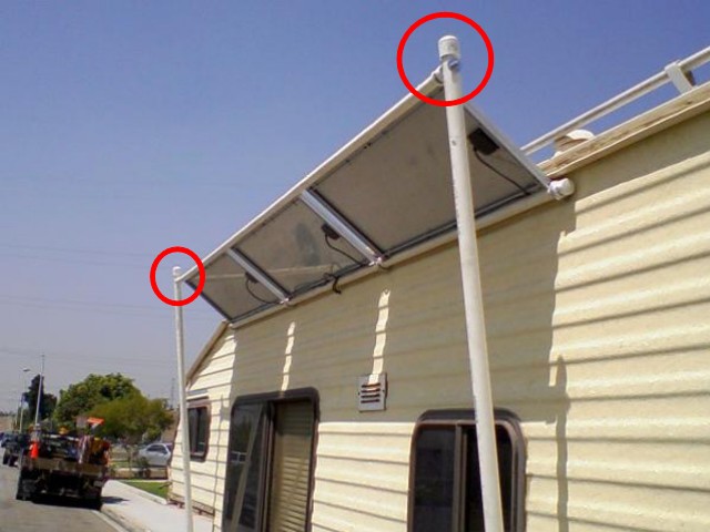
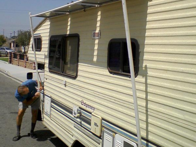
This is an example of solar power installed on a recreational vehicle (RV) or motorhome. Often the solar panels are mounted on the roof but this is an example where the solar panels are mounted on the side for easy angle adjustment. As a bonus they could also double as shade for two of the windows. This installation was done by Harvey and his father, Mel, and he has generously given permission for this information to be made available here. Any questions for Harvey can be asked of him through the Noah's Ark Energy Research (noahsarkenergyresearch) yahoogroup.
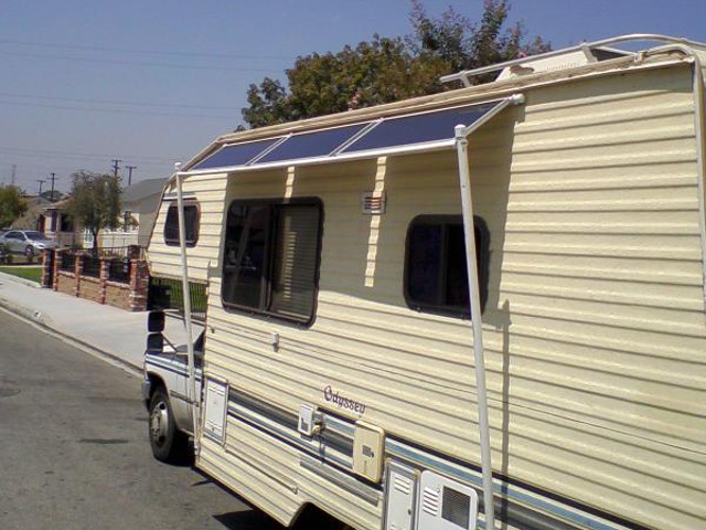
The solar system kit they purchased is a 45 watt system, consisting of:
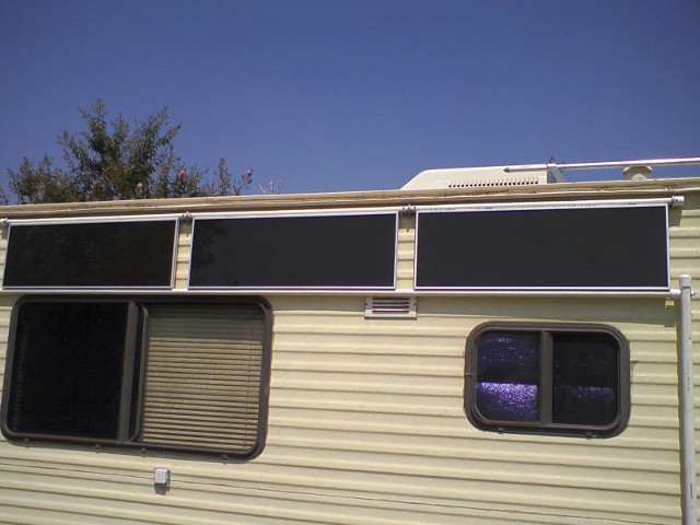
- three 15 watt panels which are connected in parallel for a total of 45 watts,
- a stand for the solar panels (not used in this installation),
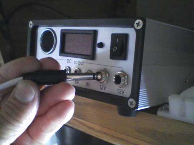
- power distribution unit (PDU) which takes the output of the solar panels and uses it to charge batteries. It also has output ports for various DC voltages,
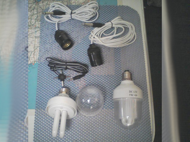
- two 12 volt DC, 5 watt lights, cables with light sockets for powering from the
PDU, other adaptors for use with the PDU, and
- cables for connecting to the batteries.
The remaining text is the write-up by Harvey. You can click on some of the photos below to see larger versions.
My father purchased this solar system from Harbor Freight in the USA.
On sale it was under $200 US for the kit. It comes with a stand but that becomes cumbersome each time it is used so my father and I set out to devise some econmical means to secure it to the motor home and allow some measure of adjustment.
Mounting the solar panels
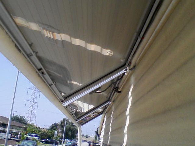
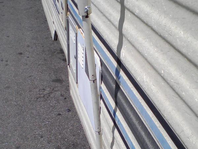
We had already drilled and tapped the solar panels with 8 holes each and mounted 3 independant pipes for the top edge and a single 10 foot pipe along the bottom of all 3 panels. Originally we had planned to use two eye bolts for each panel and make them independant for repairs. But we wanted the bolts to be hidden in the interior cabinets and this would have spread them too far apart after capping the ends of each top pipe. So on the fly we decided to insert some wooden dowel rod (turned down broom handle) between each section and screw them together. This afforded a means to remove a panel independantly but still created a unitized assembly. Measuring off the bottom pipe to align with all the pre-tapped holes in the solar panel frame was not easy. The pipe is quite flexible and measuring was problematic. I dropped nails in the 12 holes and my dad and I held the pipe in position, scoring it with the nail points. Only four out of the 12 aligned properly - so we over drilled the holes to allow for adjustment and all worked well. We did not use any glue or cement on the pipes, they are all held in place with screws. I had a bunch of self tapping drywall screws from my old hanging days and they worked well in most places. We used 6-32 machine screws to attach the pipes to the frames and a modified doweling jig with a drill guide to align the holes in the right place.
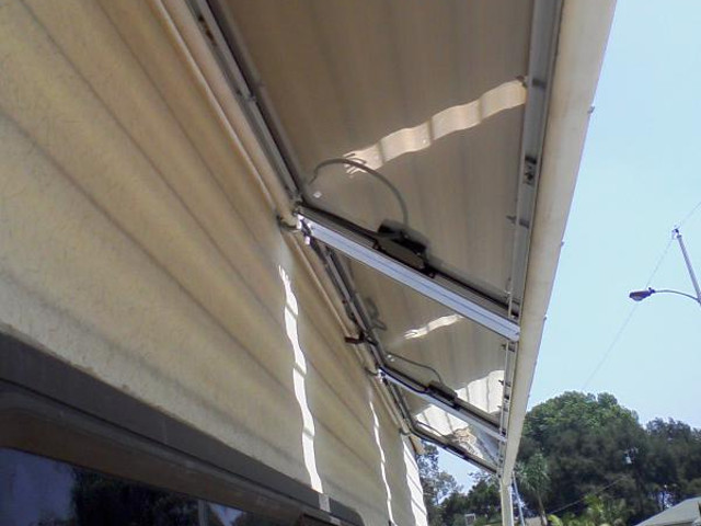
The solar panels are prewired. Even though they appear to have a connector on the back, it is doubleback taped to the glass and doesn't have a convenient means for disconnect. The other end of the wires have an eyelet crimped on, thus we drilled a hole in the RV large enough to pass them through. This also afforded room for all 3 panel wires. See the above photos. [The resulting 6 wires, 3 positive and 3 negative, were connected to the back of the power distribution unit (PDU) resulting in a parallel connection. See the photo below of the back of the PDU.]
Making the angle adjustment mechanism
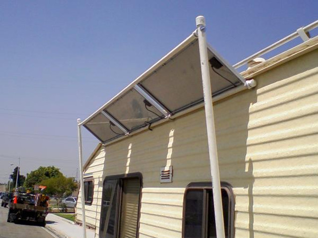
My original idea was to use pull cords and cleats to tie off the panel at various positions as necessary. Even though my father bought the pullies and cleats, it soon became apparent that this idea needed to be revamped. Securing the pullies was an issue and the idea of having cord slapping the side of the RV when driving was not a savory concept. My dad decided to browse the local Home Depot and see what might work. I suggested he look at the telescopic handles for paint brushes or squeegies I have seen in the past. He returned with some metal clips and 20 feet of sch40 PVC pipe. I looked at the clips and they were quite flimsy and suggested that we try another approach.
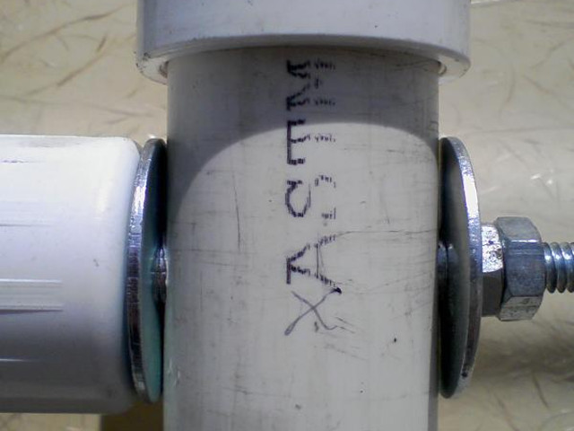
As shown in the photos below, for the upper pivot assemblies I suggested to my dad that we drill two of the end caps and insert a screw in there as a pivot. I had an old piece of chrome plated copper tubing from under a sink and suggested we use that as a bushing for the pivots. That way the threads from the screw wouldn't ride on the plastic. A properly engineered shoulder bolt would have worked also but the tubing has the advantage of allowing a tight assembly without compressing the pipe. So the upper pivots are comprised of a cap, bolt, washer, tubing, washer, nut. The large PVC pipe is between the washers with the tubing housing the bolt which penetrates all the parts. That gets rid of the flimsy u-shaped sheet metal clips from the top. But what about the bottom?
For the lower support attachments (see photos below), remember I said earlier that we intended to use 2 eyebolts for each panel but changed the design on the fly? Since we had two eyebolts left over I suggested we use those for the bottom support holders. So my dad cut two 2-1/2" pieces of 1/2" PVC, I grabbed two couplings from my pipe drawer in the garage and my wife ran to the hardware store to buy some caps (returning with two the wrong size and making another trip - not her fault, they were mismarked and the sales person selected them for her). So, voila, we secured all the pieces with screws and were ready to drill the pin locations.
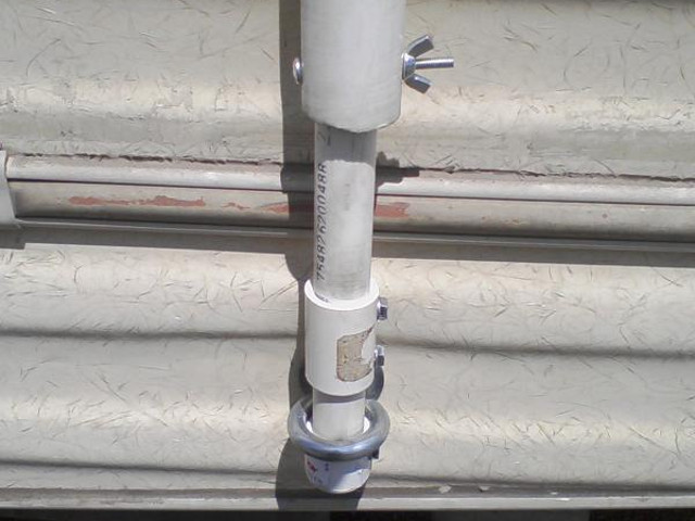
Using a carpenters square I squared the panels to the RV exterior and wedged a couple of screw drivers between the 1/2" inner pipe and the 1" outer pipe (remember those are inner dimensions so the gap isn't as great as you may think at first). The screwdrivers held well and we drilled manually through both pipes simultaneously and inserted an 8-32 screw as a pin. Then we did the other support, drilling through both of those pipes as well. Then we collapsed the assembly and drilled two new pin locations for the transit position. My dad was trying to figure a way to get a 45° hole when I explained that it had to be half way between the two holes we just did. He looked a bit puzzled at first but soon grasped the idea that a 0° hole and a 90° hole would represent the full travel and thus half way would be 45°. He quickly measured the distance and halved it, marked them and drilled them and did the same for the 45° past 90° (135°) and it all went smooth. That is until we tried to get those pins in the holes. The problem is that inner pipe is free to spin and it was hard to find the holes. Plus, if it turned 180° we were fighting the 'manual hole drilling' offset. Yay for Sharpie brand indelible markers. Once we got them aligned my dad marked them up and now its much easier.
I still think we may try to find those telescopic poles and redo that part of this project sometime in the future. But for now, it works pretty good. That 135° position allows us to catch the sun even if its on the other side of the RV.
The remaining parts
The remaining parts of the kit are the power distribution unit (PDU), a stand for the solar panels (not used in this installation), the battery cables and two lights along with the parts for connecting the lights and other loads to the PDU. Batteries are not included in the kit.
The power disctribution unit (PDU)
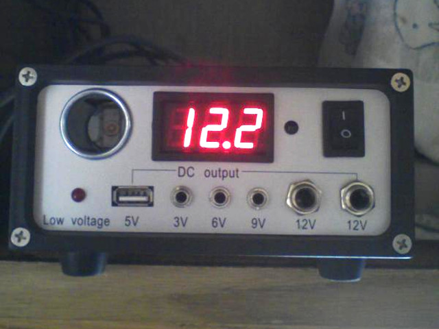
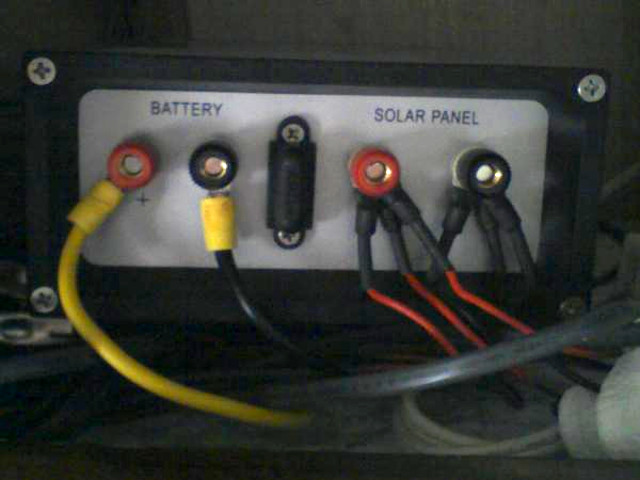
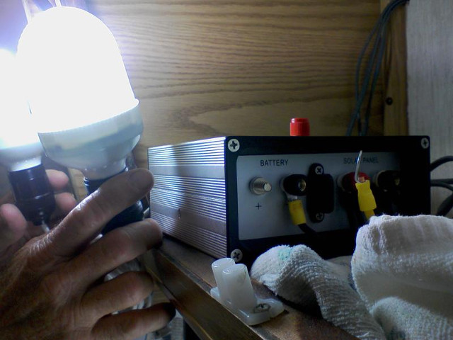
The PDU (power distribution unit) has integrated charging circuitry. I put an ohm meter to the terminals to see how they were connected and the positive (+) leads are bonded between the panels and battery. However the negative (-) leads have a diode between them. This tells me that we cannot mutually ground the negative terminals and expect it to work properly. The RV has other chargers (alternater and city power charger) for the battery as well, and we don't want these to back feed to the panels.
The tiny black button next to the switch allows you to turn off the display to reduce power drain. The PDU will still be active though.
A 4 amp fuse is provided.
The loads
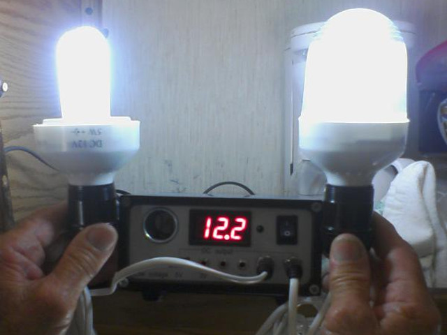
For the following photo I disconnected the battery and ran two of the fluorescent lamps off the panels directly. Although this works, I don't recommend it. The system needs that battery filter. The lamps would flicker and the recursive process of shutting down and restarting is not good for those fluorescents.
|
Do you have a project you'd like to share on rimstar.org too? You're more than welcome to. Click here for details. |
|

