How to make a Kelvin water dropper
The following talks about how to make a Kelvin water dropper, a device that converts falling water to static electricity. It's an amazing device and a cool science project. If you're unfamiliar with it you might want to watch the video on how a kelvin water dropper works at the bottom of this page first. There's also a video at the bottom on how to make a kelvin water dropper.
Parts for a Kelvin water dropper
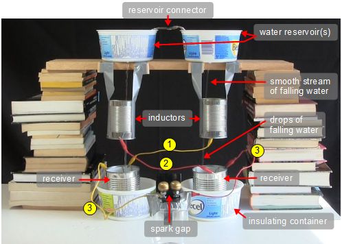
The following items are labelled in the above photos, showing an example of a Kelvin water dropper I made from things around the house.
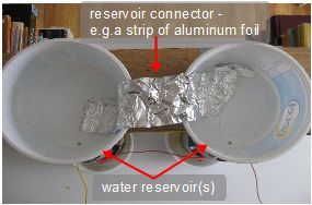
water reservoir(s): These contain the water that's dropping. Fill them with water to get it started. They each have a small hole in the bottom, front for the water to fall from. They can be made of any material. In the above example I'm using margarine containers. I have two in the above example because the inductors and receivers below them have to be separated horizontally from each other. If you have a wide enough container then you can have just one reservoir with two holes in the bottom. Since I have two, I needed to electrically connect the water in them. That's the reason for the reservoir connector (see below) which in the above example is a strip of aluminum foil.
reservoir connector: If you have two separate water reservoirs (see above) then you need to electrically connect the water in them together. In the example above I'm using a strip of aluminum foil.
inductors: The inductors are cylinders or metal rings which the water can fall through. That means if they're made out of cans, as in the example above where two soup cans are used, then both the bottoms and tops must be removed. They are positioned so that the water falling into them is a solid stream and the water falling out of them is in the form of drops. With the naked eye it's hard to see individual drops but if the water looks turbulent to the naked eye then it's actually many individual drops.
receivers: These are metal containers that the water drops into. Note that they should have a fairly wide opening since the water falling into them may be a wide spray. In the example above they weren't quite wide enough so the insulating containers (see below) helped catch water.
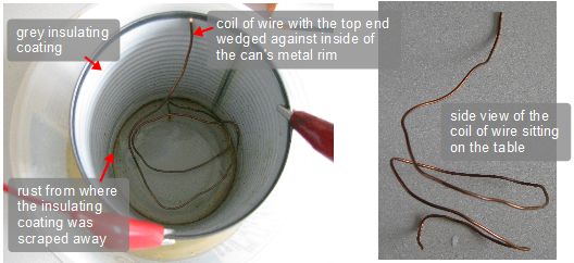
The insides of the receivers must also be metal, not insulated. In the above example I used bean cans and they had a grey coating inside that was electrically insulating so I had to scrape some of it near the bottom to expose the metal. But that caused a rust problem (see photos below.) I'd left water in them for a day and by the end of the day I couldn't get a good spark anymore. The rust had made the exposed part no longer conductive. So I scraped it some more. But to help further, I coiled up some bare copper wire (see photos below) and put it inside with the top end wedged against the inside edge of the can's metal rim. Again, this was necessary only because I used cans that had an insulating coating inside and was made of a metal that rusts.
insulating containers: These are to keep the two receivers from electrically conducting to each other. As such they must be made of an electrically insulating material, like plastic. In the above example I'm using margarine containers. Why would the receivers coduct to each other if they're spaced apart? The table may be conductive or the table may get wet and then that water will conduct. If neither of those will be the case then you don't need these insulating containers. I needed them because my laminated table was partly a conductor and because it got wet over time.
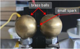
spark gap: The spark gap is where the spark occurs once the electrostatic charge has built up on the various parts. In the example above I'm sitting it on top of a plastic jar to avoid any electrical conduction across my wet, laminated table. The two sides of the spark gap should be smooth. Two rounded bends in thick wires placed about 1 or 2 millimeters (1/16th to 1/8th of an inch) apart might be good enough. In my case I used two brass balls (see the above photo). Adjust the space to whatever works. Start with a very small spacing.
connecting wires: In the above example I'm using wires with alligator clips on each end. Use whatever you have. They are connected as follows:
- right inductor to left receiver
- left inductor to right receiver
- right receiver to right side of spark gap
- left receiver to left side of spark gap
Tips and tricks for making it work
The order of construction
Prepare the reservoir(s) first. As mentioned above, the inductors should be placed over the area where the falling water changes from a solid, smooth stream to individual drops. Part of what determines where that is is the size of the hole in the reservoir. The bigger the hole, the farther down that transition from stream to drops will be. So get your reservoir, make a small hole and let water fall from it. See where the transition happens. Is it far enough down so that you can fit your inductor there? It may be only a half inch below the hole! If it's not far enough, make the hole a little larger and try again. Keep doing this until the transition point is far enough down so that you can fit your inductor in place.
Vertical location of the inductors
Make sure that the water entering the inductor cylinders from the top is a solid stream and that the water coming out of it is not. The water coming out the bottom should be individual droplets, though it's too fast to see that. It may just look like a turbulent stream to the naked eye. To really see the droplets you'd need to need to take a high speed photo of it or film it with a high speed camera to see that. I show that in the hot-to-make video below at 1:00. So play around with the height of the inductors in the stream. Both inductor cylinders may be at different heights.
Placement of the stream in the inductor
In order for the charging of the stream to take place, the stream must fall fairly close to the inside wall of the inductor. Even though in the above example I used soup cans for the inductors, the stream ended up having to pass only about 1 centimeter (1/2 inch) from the inside. So you don't need big diameter cans. It will take a lot of adjusting to get this right.
Size of the inductors
The inductors are there just to repel charge up the solid stream. They don't have to be tall to do that.
However, as said above, they should be located over the area where the water changes from a solid stream to individual droplets. Making them a little tall does give you more of a chance of being at the right spot, since as long as the change happens somewhere inside them then you're good.
But if you do make them tall then give them a big diameter too. If the water turns into droplets somewhere inside the tall inductor then the droplets will spread out and touch the inside walls of the inductor and give them the opposite electrical charge that they should have and make it not work.
Possible coating in the receiver cans
There may also be a coating inside the cans that are sitting on the table that could be interfering. The coating may not be visible. Use a sharp object (e.g. the tip of scissors or a knife) to scrape some of the coating off inside those cans. The areas you scrape should be areas that are under water. If the can is steel or anything that contains iron then the scraped part may rust over time in the water. If it rusts then scrap it again.
The spark gap
The parts of the two objects that face each other at the spark gap should not be sharp points. They should be smooth. That's why I used two metal balls. You can find rounded drawer handles in hardware stores but make sure you scrape off any possible coating where you connect wires to them and where they are facing each other.
Put a dark background behind the spark gap to see faint sparks.
Try with a very small spark gap.
Conductivity of the water
Adding an electrolyte to increase the conductivity of the water doesn't appear to make any significant difference as the following experiment demonstrated.
An 8th grade student named Austin from northern Kentucky did an experiment to see if using an electrolyte solution with all the extra ions will make a difference in the charge rate, and his grandfather shared these details with me.
The above chart shows data for 6 different test runs, 3 with just plain water and 3 with salty water. For each test run, a video recording was made of the spark gap for observing the length of time between sparks in seconds. The above charge shows the results for 10 sparks per test run.
The 3 salt test runs were (as close as possible) 0.1 molar, 0.2 molar and 0.3 molar solutions of salt water (6, 12, and 18 grams each in a liter of water.)From watching the video it appeared there was no change in the data - i.e. Each spark was roughly 5 seconds apart. But from the exact data they found that there may have been some slight improvement in charge rate (between 3% and 12%). Still nothing much compared to the increase of ions by a factor of a million! (0.1 molar versus 10^-7 molar for pure water) And as you can see, going from 0.2 molar to 0.3 molar didn't seem to change anything.
Video of how the Kelvin water dropper works
The following video demonstrates the Kelvin water dropper in action and gives a detailed explanation of how it works.
Video of how make a Kelvin water dropper
The following video goes step-by-step into how to make your own Kelvin water dropper along with tips for troubleshooting it.
