Potato chip macrochip with 555 timer circuit
When I first heard there was a microchip manufacturer called Potato Semiconductor Corporation I immediately knew I had to try to put an electronic circuit on a potato chip, to make my own 'microchip', or 'macrochip', so-to-speak. And so I did. You can see it in action in a video below.
I'm not sure where I got the following from, I'd saved it away long ago but it's nice to see the humor.

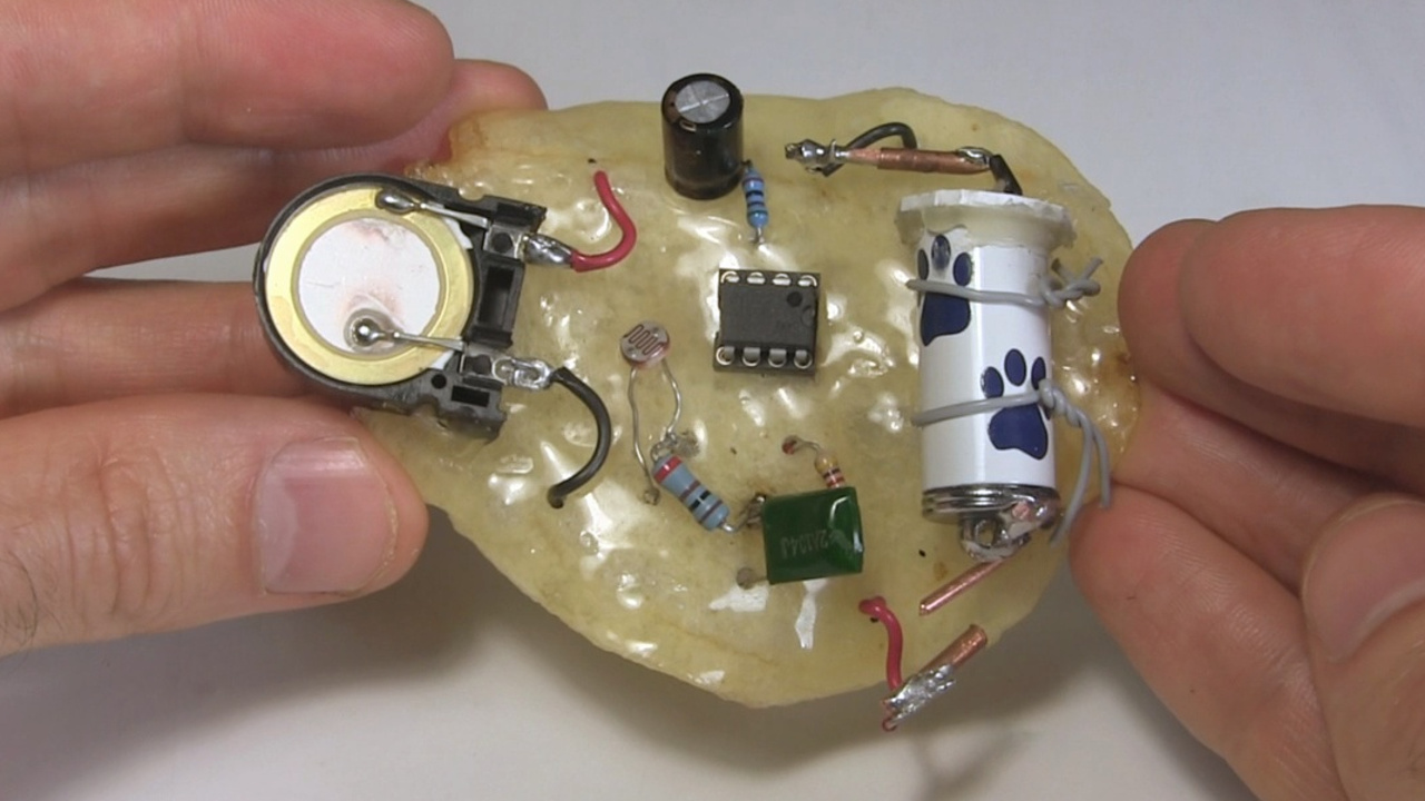
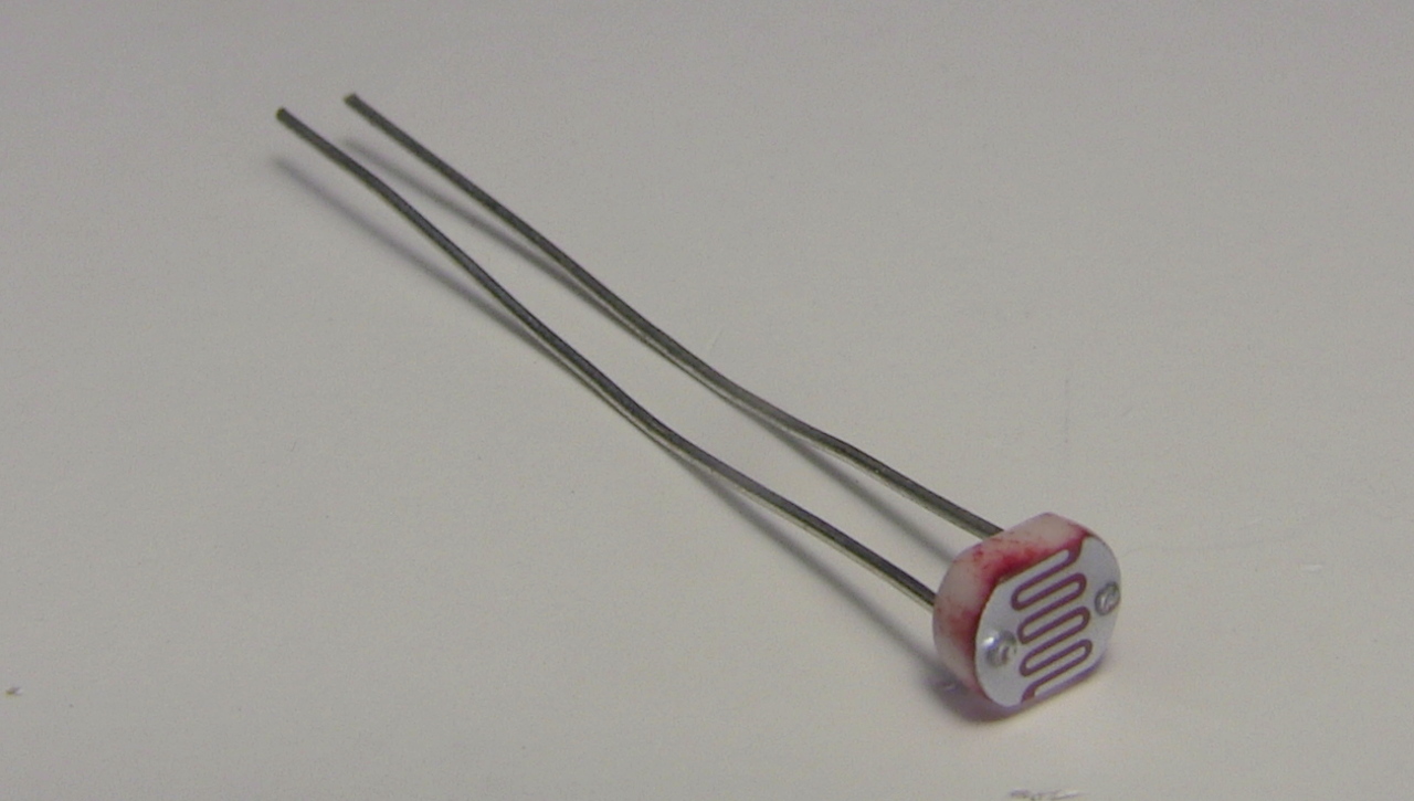
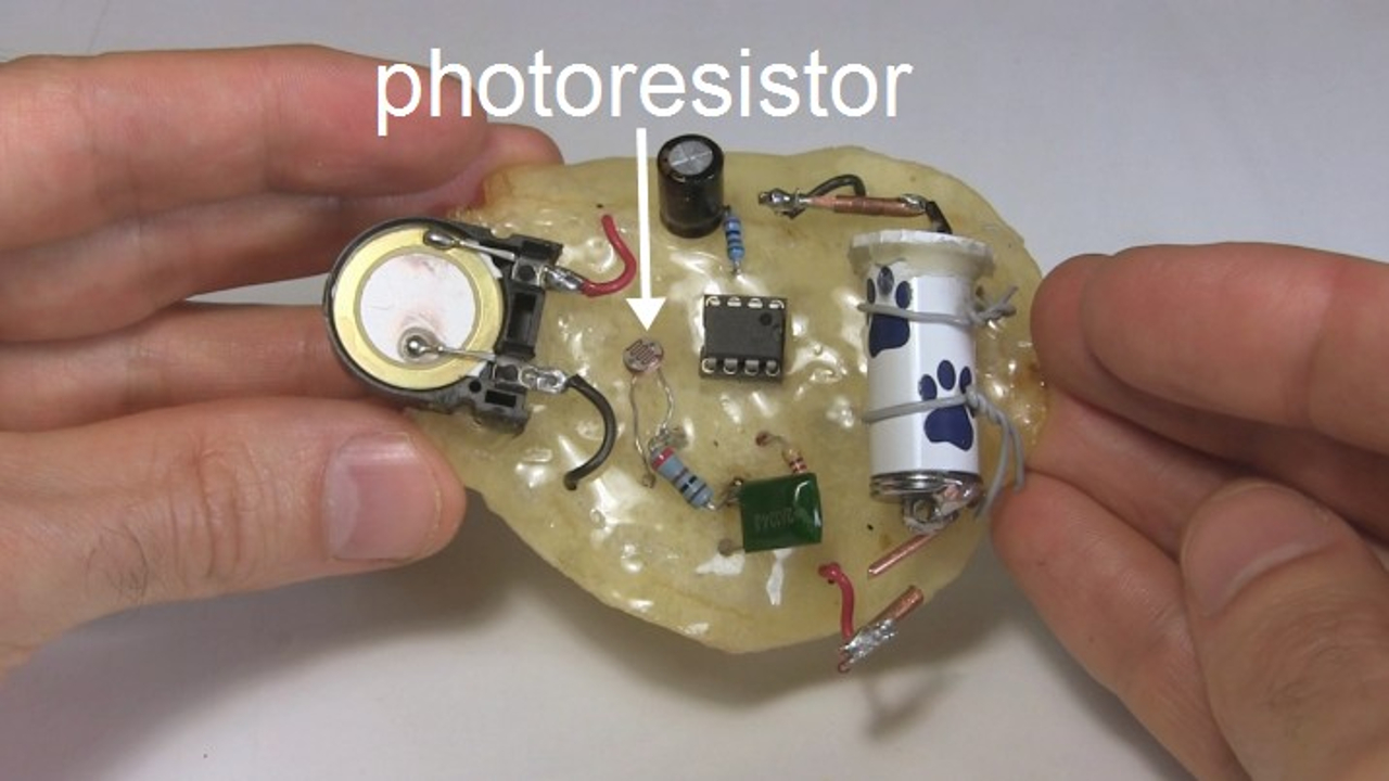
For the circuit I wanted something fun that would make some sense. Drawing on my experience with my music player projects, I came up with the idea of having a 555 timer circuit that would play a sound and use a photoresistor to vary the frequency of the sound. The photoresistor is a resistor, as the name implies, but its resistance depends on the amount of light it receives, hence the 'photo' in the name. With the 555 timer circuit, the resistance between pins 6 and 7 is part of what determines the output frequency and therefore the sound. So the photoresistor went there.
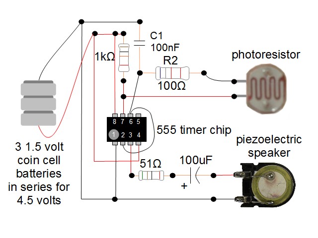
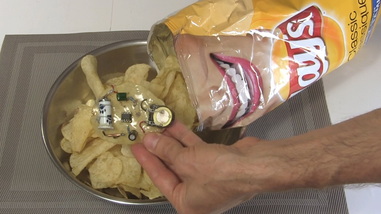
The result is that you can put the macrochip in the bottom of a bag of chips and the sound would be one frequency (it ended up being a ticking sound, as if there was a bomb in the bag). Then as you remove chips from the bag, the photoresistor gets more and more light and so the frequency changes, until finally you dump it out of the bag and by then the sound is a squeal.
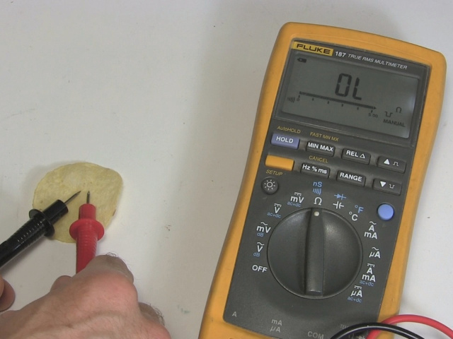
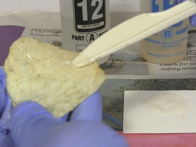
I made sure to get plain chips, non-salted, since salt or other ingredients could make it electrically conductive. Once I found a big enough chip, I tested the resistance with a meter to make sure it was infinite resistance. To make the chip solid enough, I coated it in 2 coats of clear epoxy resin and waited a few days to make sure it was stiff.

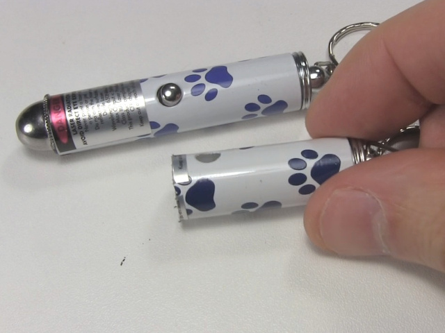
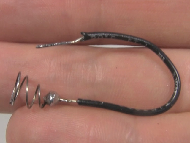
One notable component is the battery. I needed around 4 or 5 volts for the circuit but I needed the batteries to be small and lightweight. For my previous laser communicator project I'd already come up with a way to take apart a pet toy laser from a dollar store and modify the case to use as a battery case. It contained 3 1.5 volt coin cell batteries connected in series for 4.5 volts and so it was perfect. Below is how I did it.
Inside the case is a spring, which I removed and soldered to a wire. I then cut a plastic disk with a hole in it and hot glued the wire into that hole.
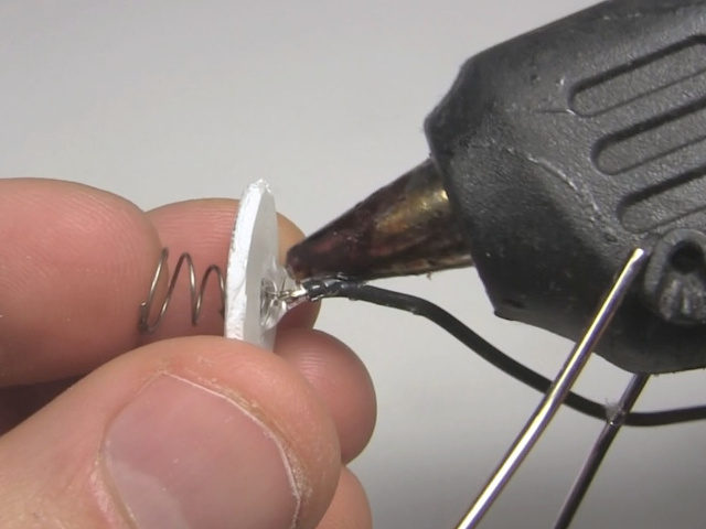
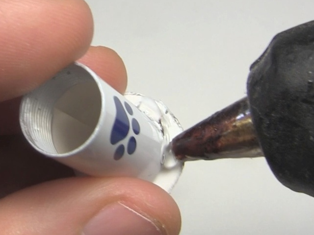
This was then hot glued to the end of the case.
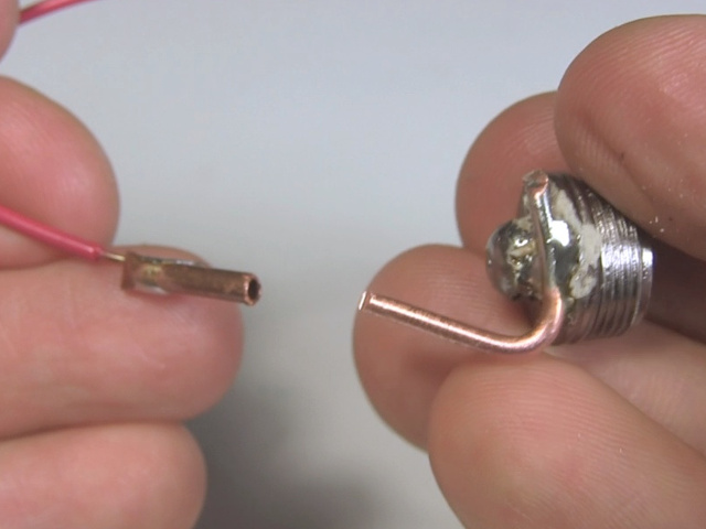
I also needed an on-off switch, and so I soldered a thick wire to the endcap for the case. The endcap has a non-conductive coating on it so use acid (flux) when soldering to make sure to penetrate the coating. A copper tube from a hobby store fits snuggly over that thick wire, basically making a plug.
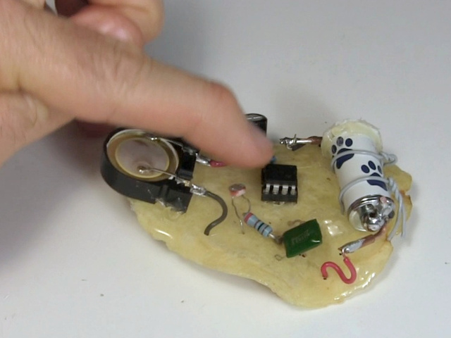
You can see the finished result below.
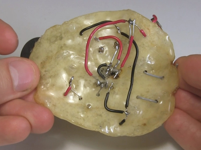
The chip was solid enough to drill holes for mounting components. The first thing I attached were some wires for holding the battery case in place.
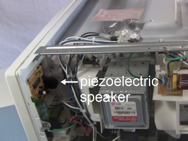
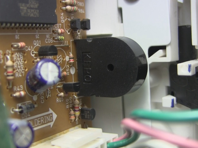
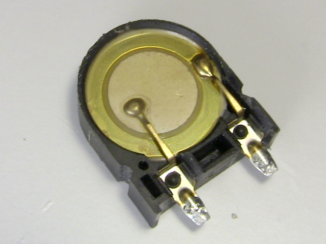
The speaker was also an interesting component. For that I use a piezoelectric speaker taken from a microwave oven. This is the same thing I did for making an earphone for a crystal radio.
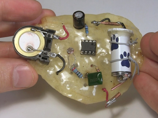
The top and bottom views of the finished result are below. You can test it by using your finger to block the light going to the photo resistor. Different amounts of light give different sound frequencies.
Video - Potato chip circuit/macrochip with 555 timer circuit
The following short video shows the making of it as well as demonstrating it in use, controlling the sound using a hand and with a bag of chips.
