This is an analysis from photos and videos of the 3kW machine's sector's geometry.
The point of this analysis is to be able to make grids that closely match the
testatika so that similar frequencies will be generated.
How many sectors?
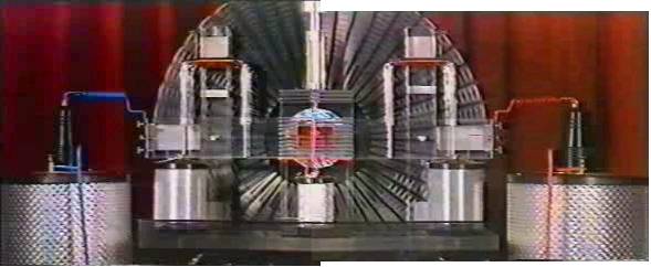
The following composite photo is made up of snapshots of
two sequences put together along with some grafting so that an accurate
sector count can be made. It appears as if there are 48 sectors (previous
estimates by others said 50) or groups of sectors depending on your meaning
for the word sector. With one meaning, as you'll see from reading below, there
are actually 288 sectors, organized into 48 groups and with 48 wire grids attached
to the front of the sector groups.
Click on the photo to see the ungrafted version.
 |
|
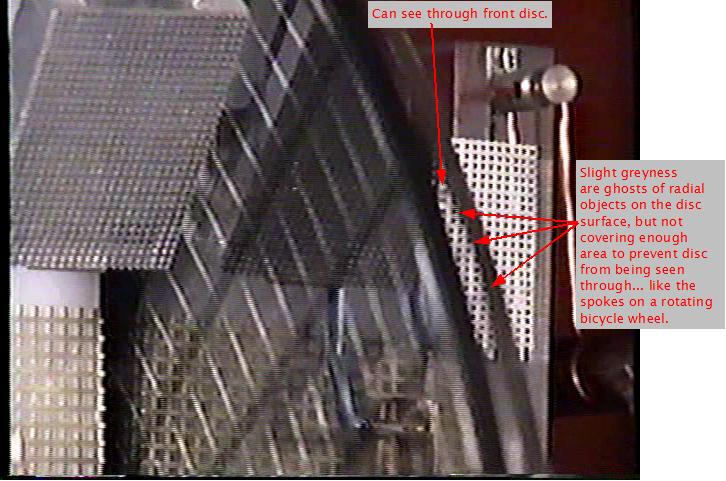
Front sector is see through (at least when rotating)
Have a close look at the following picture. It is from the DVD version
of the Methernitha video and is also on the VHS version but is not on
the online version.
Click on the photo to see the original version.
 |
|
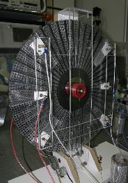
Some hints may be gotten from the following device which is shown in the
lab at Linden near the beginning of the amateur video. It occurs when
they are talking about multiple discs in tandem. No details about the device
are given though.
Sectors near the disc edge
Here is a snapshot taken from the Methernitha video. Note the unexpected
appearance of the sectors as thick wire with flat strips of metal behind them.
The above appearance is an illusion brought about by the fact that there
are two counter rotating disks and the camera shutter speed.
The following two photos show the true shape of the sectors. The first
photo is taken from the rear and the second from the front. In the
first photo either the disks were not rotating at the time or
a very fast shutter speed was used. In the second photo the disks
are rotating but the shutter speed was fast enough to capture the sectors
as they really are. Click on the photos to see the originals.
This excellant analysis was done by Elena from the testatika Yahoo! Group
and explains how the above illusion comes about.
She finds that an almost identical appearance of these wire-type sectors
would arise from very different actual sectors at certain shutter speeds
relative to certain RPMs when you have two counter rotating disks.
The front disk would be transparent and the
rear disk would be opaque, both of which are widely agreed upon. Further,
the rear disk would have sectors on both sides, meaning that the sectors
that are on the front facing side of the rear disk would be visible
through the transparent front disk. Albert Hauser also stated that there
were sectors (lamellas) on both sides of the rear disk in his visitor report.
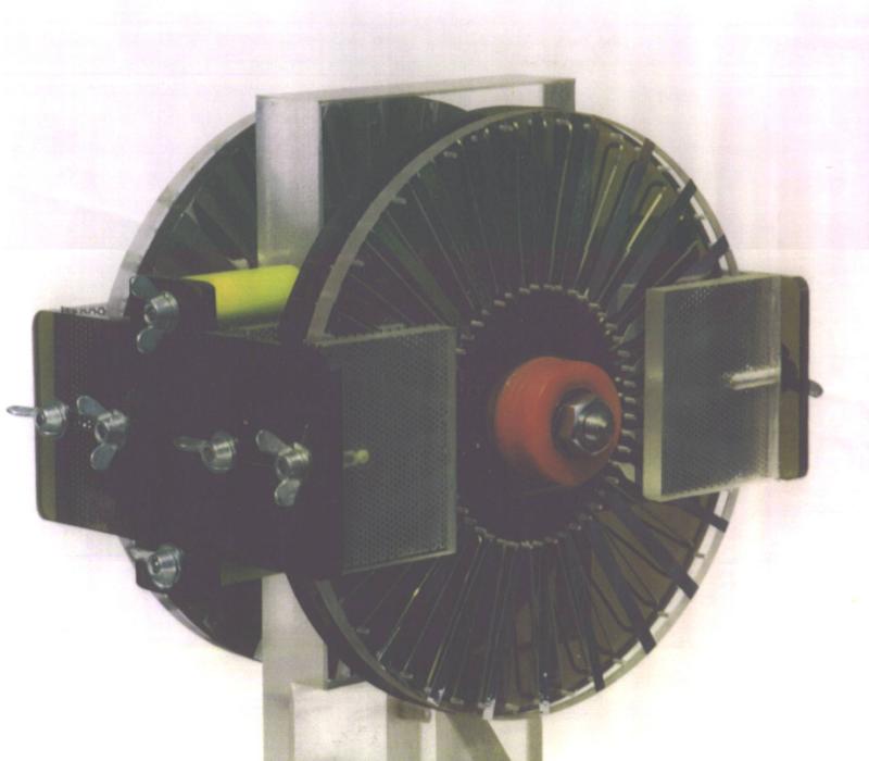
The following are the sectors on her machine, which are nothing
like thick wires. Note that there are two disks in
the photo, both having the same type of sectors.
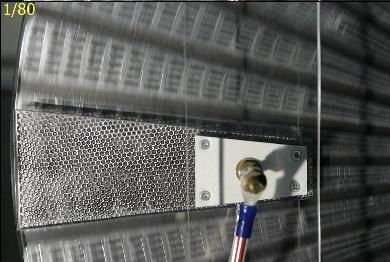
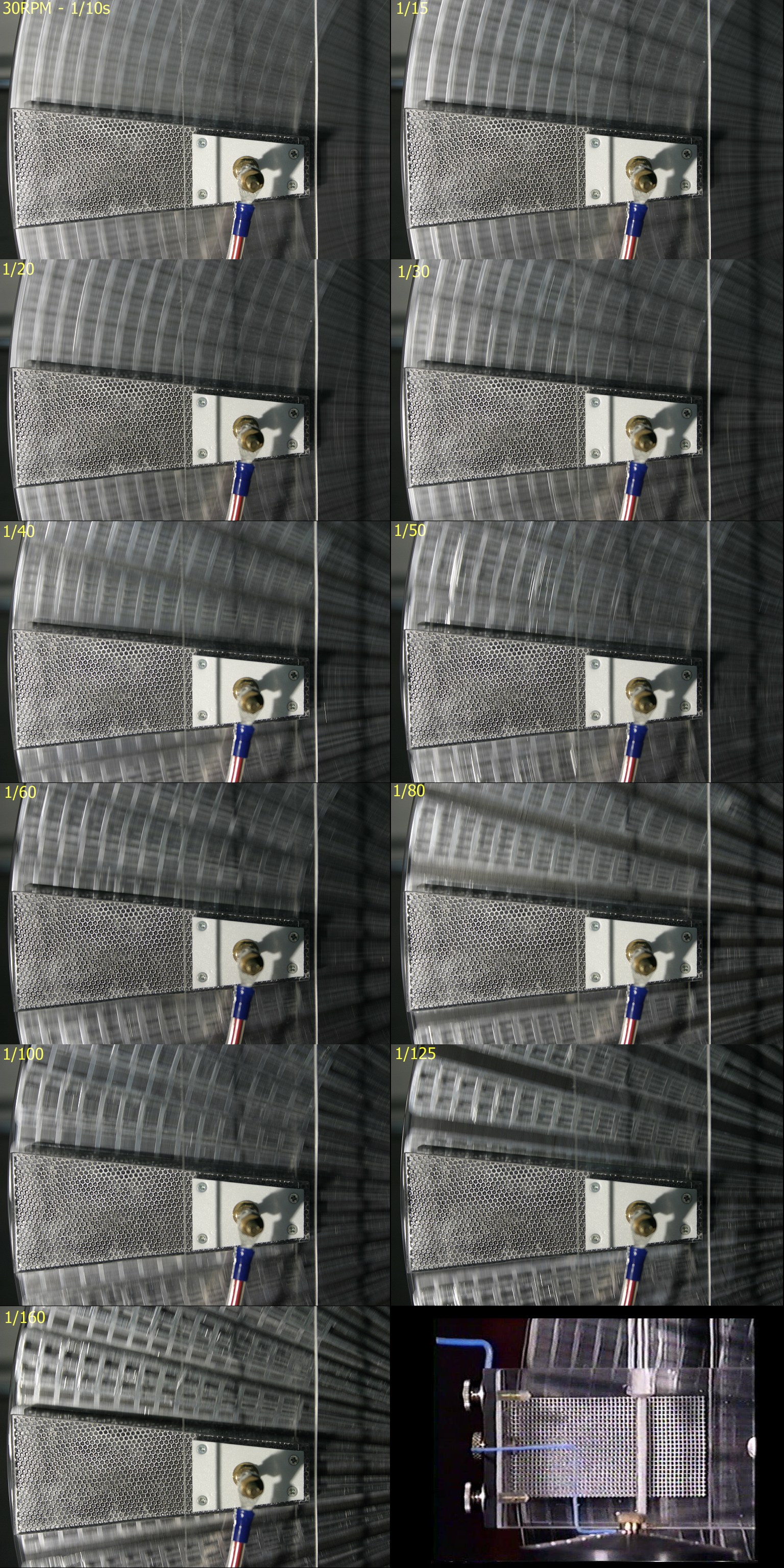
The photo on the left below is of a portion of her disks spinning at
30RPM, which is how fast she has concluded the 3kW machine disks are
spinning. The shutter speed is 1/80. Note the similarity to the same area
of the actual 3kW machine in the photo on the right and how different it
is from her actual sectors in the photo above.
The following is a collection of the above types of photos that Elena
took at different shutter speeds. Click on the photo for the full size
version.
Click on the photo to see the full sized version.
 |
|
Thank you to Elena for allowing me to share her analysis here with
everyone.
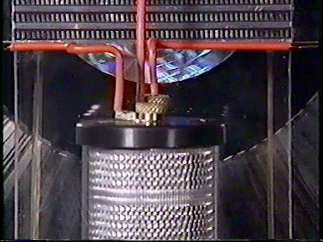
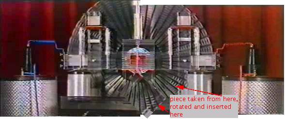
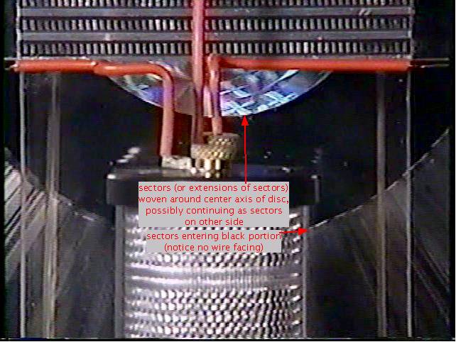
Sectors near the disc center
Next, the sectors seem to enter a black area on the disk and may reappear
at the center to form a mesh. The sectors here are blurred as a result
of being taken from a slow speed video but their individuality near
the center
can be seen in the above photo with the bright lightbulb where the
camera shutter speed was much faster. Note that if
there are 1Kohm resistors connecting the sectors near the center of the
disk as some say was stated by Paul Baumann then the
black area is a likely place for the resistors to be.
Click on the photo to see the original version.
 |
|
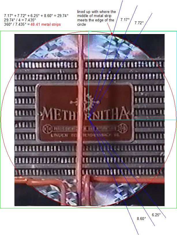
The following photo as an analysis that pretty much proves this.
From above it's shown that there are 48 sectors. By measuring the
angle between where each clear adjacent wire strip enters the black
area and taking the average of those angles, we get an angle,
7.435 degrees, of which there are 48.41 in a full circle of 360 degrees.
This is very convincing evidence that each strip is connected
ultimately to a sector.
Click on the photo to see the original version.
 |
|
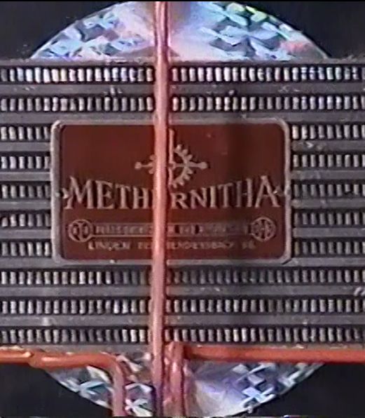
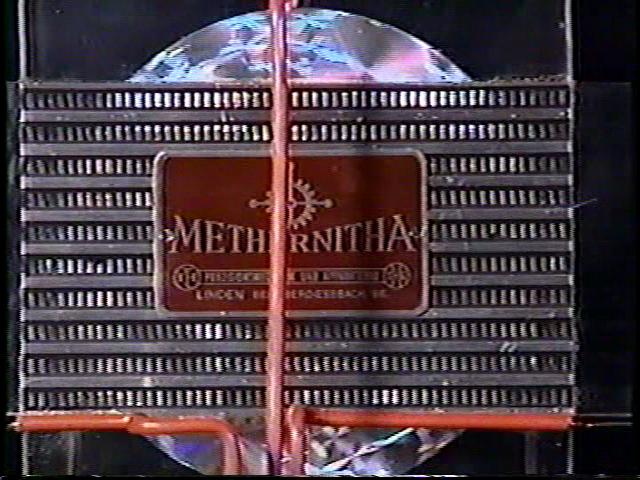
This is often mistakenly refered to as a "hologram" that was placed
here for appearances only. The shiny, rainbow appearance is due to
the shininess of the metal strips and the fact that they are twisted
together, causing surface curvature in the metal which reflects
through the clear plastic or glass as multiple colors.
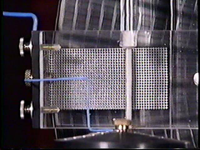
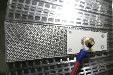
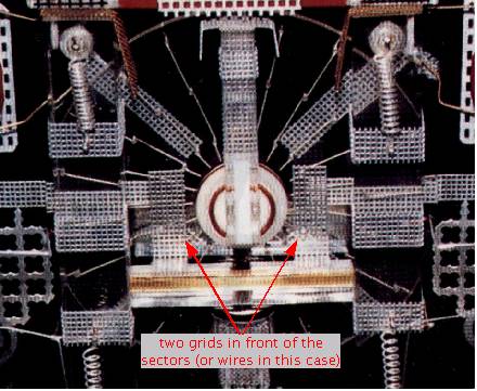
Grid in front of the mesh
Lastly, there is a grid in front of the mesh.
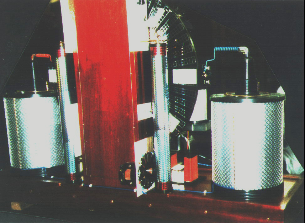
This same sort of grid in front of the sectors near the center is also
found on the single disk small machine as the following photo shows
(in fact a lot of components can be found in similiar places on both
machines.)