|
|
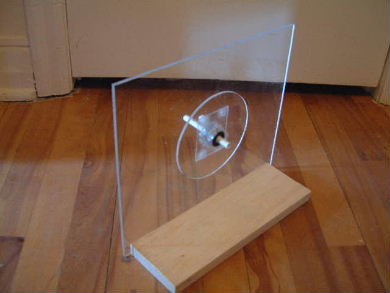
Bare disk on bare stand.
 |
|
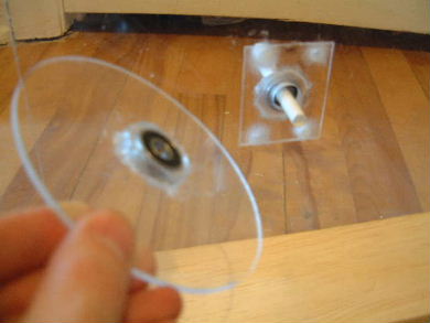
Showing what part is stand and what part is disk.
The stand and disk both have a bearing epoxied to them.
 |
|
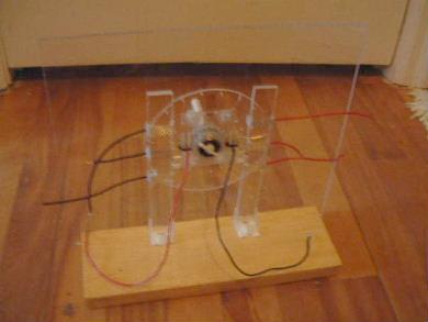
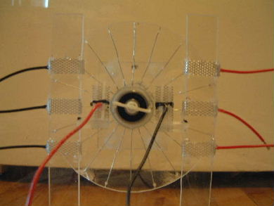
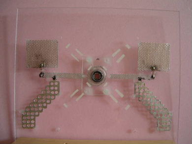
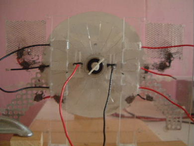
April 7 - This disk has the wires attached and the
grids that face the disk have been put in place along with wiring
suitable for test purposes. The disk wires are steel (D'Addario XL electric
guitar string, 0.020"/0.51mm diameter, G string).
 |
|
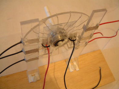
April 7 - Close up. Note the way the wire is
threaded through the face of the disk. This is likely done because
there will also be grids mounted behind the disk. Note also the shape
of the side grids. They've been wired from the side so that they can
be flipped around to have their flat end on the side facing the disk for
experimenting purposes.
 |
|
April 7 - Close up, front view. The grids have been
mounted such that when a wire approaches the bottom, inner corner
of a lower, side grid, it also approaches the bottom, inner corner of the
corresponding center grid by the same distance.
 |
|
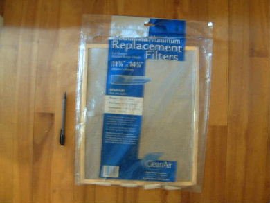
April 7 - The grid material used for the front
grids (all the grids installed so far) came from a package of filters.
The are aluminum.
 |
|
April 7 - Close up.
 |
|
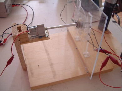
April 13 - I added a motor to the back of the
machine. It came as part of a kit commonly found in hobby shops. It is
the TAMIYA Planetary Gear Box set with RC-260 motor capable of operating
on 3 volts, not more than 4.5 volts, current 1.0A and on-load speed of
10,500 rpm. I chose a 4:1 gear ratio as that was its configuration for
maximum possible speed and the disk is not a big load. I'm powering it
with my 24 volt power supply
and controlling the speed with a variac.
 |
|
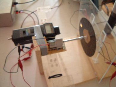
April 13 - I mounted my phototachometer beside the
motor so I can accurately measure speed. Note the cardboard disk that
has been mounted to the shaft just this side of the small machine backplate.
You can see the light from the phototachometer shining on the piece of reflective
tape on the cardboard disk (the rest of the disk has been blackened using
black electrical tape).
 |
|
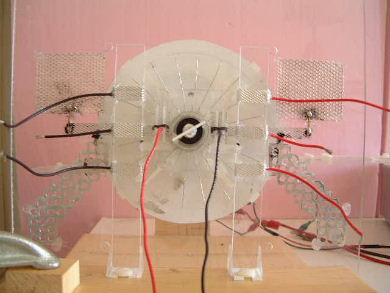
April 18 - I added most of the grids to the back
plate. Note that all the grids to the right of the center bearing are
electrically connected together and all the grids to the left of the
center bearing are electrically connected together. I didn't put them
all on yet because I wanted to test just this combination first though
you can see masking tape marking the location for four more. The oddly
shaped grids on the bottom-right and bottom-left are aluminum flashing
(0.01" or 0.02mm thick) which I've cut to shape and drilled holes into.
 |
|
April 18 - The grid material for the grids on the
top-left and top-right were made from this which I got from Home Depot.
It is a filter which was just lying around. They didn't know which
machine it came from so they just sold it to me with a part number taken
from one similar to it. The aluminum is paper thin.
 |
|
April 18 - The whole thing reassembled and ready for
testing.
 |
|
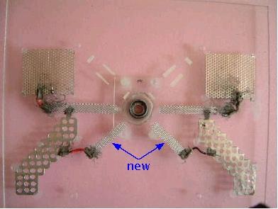
April 25 - I added two more diagonal grids on the
back and connected them to the large holed grids. I also redid all connections
to get less resistance.
 |
|
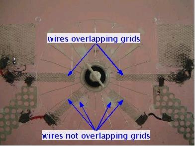
April 25 - Note that when the wires are lined up with
the horizontal grids they are not lined up with the diagonal grids. The reverse
is true when the wires are lined up with the diagonal grids. This appears
to be the way it was in the testatika small machine judging from photos and
videos. The angle between the grids on the right was about 43-45 degrees.
 |
|
April 25 - The whole thing reassembled and ready for
testing.
 |
|
|

