This is a theory along with actual tests for how the testatika produces DC from the pots (the two large cans or capacitors.) It assumes that what Stefan Marinov said he saw in the 300W small machine pots is correct and that what is said in the visitor's report regarding 20 layers of perforated sheets is correct. See the first part of the Testatika Pots (Mk2) page for details about these claims as well as details of how the pots used in the testing below were made.
The following diagram illustrates the wiring for getting DC.
|
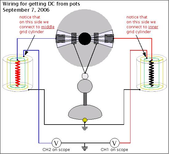
Notice that the pots above each have three concentric grid cylinders surrounding the center spiral wire electrode. As wired, the above pots are capacitors with the two capacitor electrodes being the center spiral wire and the outermost grid cylinder. The two other cylinders are floating in the resulting electric field.
The output consists of the blue wire and the red wire, each connected to one of the two other cylinders. For the pot on the left, the blue output wire is connected to the middle cylinder. For the pot on the right, the red output wire is connected to the inner cylinder. These are the output cylinders.
When a load is connected to these wires, or they are connected at a common point as in the above diagram, then the two cylinders are electrically connected. If the electric field were stationary then the field would just change to accomodate the two electrically connected cylinders. The electric field would be slightly different overall in the two pots but would be the same at the location of the two output cylinders. This would be a dead short and no current would flow over the output wire and there would be neither DC nor AC.
However, with the testatika the electric field is NOT stationary. It is likely being constantly pulsed with DC pulses. During that pulsing there will be times when the two output cylinders are at different potentials within the field and so current would flow. The result would be pulsed DC (at least that's the theory.)
Testing the Theory
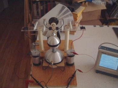
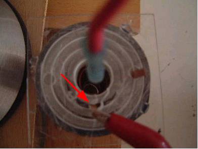
To test the theory, I duplicated what is in the above diagram, including pots with three cylinders each. One of the pots had separate external connections for each of the two possible output cylinders as shown photographs below. More details of this setup, but with cylinders wired differently, can be found at the Testatika 276mm Disk, 1st Grids - 1st Tests page.
|
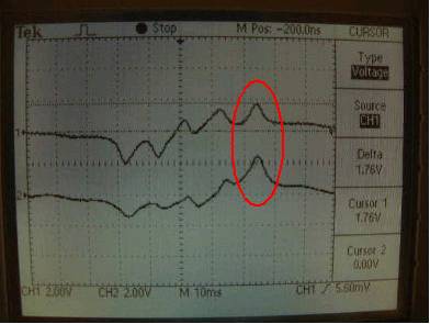
The first test was done with the output wires both connected to the middle cylinders as shown in the photo below. This means that even with pulsing the cylinders would remain at the same potential with respect to each other (ignoring variations in what's going into the pots from the disc due to imperfect construction.) The circled peaks in the scope output below fluctuate around this point, never deviating very far.
|
|
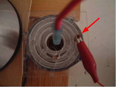
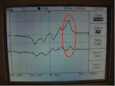
The second test was done with the output wire for the pot on the right connected to the inner cylinder as shown in the photo below and the diagram above. The pot on the left was still connected to the middle cylinder. So now, during pulsing of the electric field there are times when the two cylinders are at different potentials and so current would flow. In the scope output, the top trace is for the pot on the right and the bottom trace is for the pot on the left. Notice that at the peaks the inner cylinder of the right pot is at a significantly higher potential that the middle cylinder of the left pot even though they are electrically connected. Also interesting is that the output cylinder for the left pot (the bottom trace) is a lower potential than in the scope output above. So one side has gone up at the expense of the other going down. Also important is the first two peaks for each trace are mostly unchanged from the scope output above.
|
|
Other Discussion
The scope traces you see in the above photos, that consist of four peaks, correspond to the passage of the three sectors. More about this correspondance can be found on the page regarding the 1st tests of this setup. It is hoped that if the entire disk were covered with sectors then the peaks would remain positive. Currently the first peak is negative, the second is usually positive, and the third and fourth are always positive.
This test does not demonstrate excess energy output. It's hoped that at some point in enhancing and tuning the cylinders and disc that excess energy will just start happening due to something going on in the cylinders. But that's another theory. The object of this one is just to show how to get DC.
Note that the output is pulsed DC. The videos of the testatika that show analog meters hooked up to the output show steady DC. However, my hope is that with output that always stays above a certain DC voltage and then has additional high frequency pulsing on top of that, the output on an analog meter would look pretty steady at an intermediate level as the meter's needle would not be able to respond fast enough to the high frequency pulses.
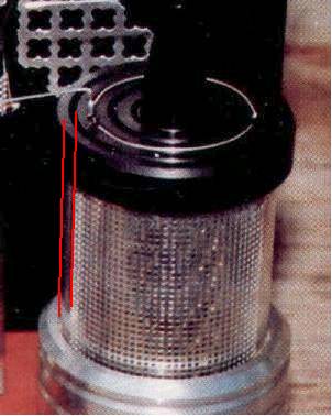
Lastly, in the 300W small machine, Stefan Marinov said he saw only a single cylinder and therefore this trick would not work. However, possibly he wasn't counting an outer cylinder, thinking of it instead as a cover. The other cylinder would then have been of different diameters in their respective pots. The following photo with added red lines is an attempt to analyse this. Another possibility is that the spiral wire electrodes at the center were of different diameters.
|