
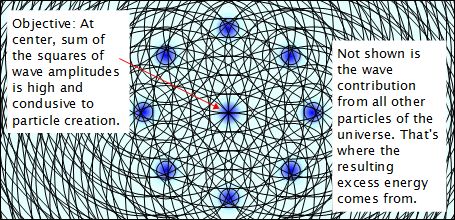
As was shown on the theory page the general idea is to create non-linear areas of space that are condusive to charged particle creation. The approach to doing that in the designs below is to use capacitors where one or more plates of the capacitors are mesh or perforated plates; basically capacitor plates with holes in them. If the plate is charged to one polarity, positive or negative, then each hole will be surrounded by particles of one charge and the wave density in the center of the hole will be large. That large wave denisity is where space would be non-linear and particles may be created.
|
Some sort of cycling would be needed so that during one part of the cycle the particles would be created, and during the next part of the cycle the particles could escape through the load.
Since particles have spin, a magnetic field of some sort may need to be present to 'initiate' that spin.
1st approach - Using spark gap and one canister (January 14 2010)
The first idea is to use a spark gap to produce the fluctuations as in the following diagram.
|
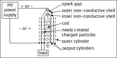
There is a unidirectional high voltage electric field across the two output cylinders. This is provided by the two electrodes: the outer cylinder and the coil. The purpose of this is to provide the necessary electric field for particle creation but also in case both positive and negative particles are created. The positive particles will be attracted to one output cylinder and the negative particles will be attracted to the other output cylinder. The electric field acts as a sort of diode for the newly created charged particles.
The purpose of the inner and outer non-conductive shells in the diagram above is to trap any ionized air and direct it down to the area between the output cylinders. The ionization would occur due to the arcing in the spark gap. The ionized air would hopefully help in transporting newly conductive particles to their respective output cylinders. Note that this also results in false current measured through the load as this ionized air creates electrical current between the output cylinders.
Charged particles could actually be created on either side of each output cylinder, as the following diagram shows. However, due to the unidirectional pull of the electric field positive particles would be pulled to one side of a cylinder and negative particles would be pulled to the other side to that same cylinder, thus negating each other. For this reason, as the following diagram shows, insulation is fixed firmly against the outside surface of the outer output cylinder and against the inside surface of the inner output cylinder to block particles that are created on those sides.
|
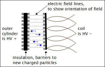
It may be advantageous to keep the arc as unidirectional as possible. This may be helped by putting strong magnets on either side of the spark gap, quenching the arc.
2nd approach - Steady HVDC with smaller pulses (February 1 2010)
The second idea is to maintain a more steady electric field across the output cylinders and have smaller fluctuations on top of that. This approach replaces the spark gap of the first approach with some other pulsing mechanism. This could be a solid state pulsing circuit or a rotating variable capacitor.
|
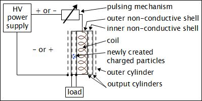
Note that there is still the use of the non-conductive shell since some newly charged particles will not reach the output cylinders but will ionize air instead. Keeping these may be advantageous for increasing the conductivity of air between the output cylinders.
It's also important that the current during the pulse be sufficiently high so as to create a magnetic field between the output cylinders. This provides the initial spin required for particle creation. This magnetic field could be augmented by placing a rod magnet in the center of the coil. However, care has to be taken that this permanent magnetic field doesn't result in the particles rotating around the cylinders as the would in a E X B field combination, where the direciton of particle motion is at right angles to both the electric field (E) and the magnetic field (B). This is the advantage of a strictly pulsed magnetic field where particles are created during the pulse and then travel to the output cylinders under the influence of the remaining steady HVDC electric field.
