Combined results of my visits
The same information below appears broken up by date of visit further down. I've reordered the information so that information about related parts are close together. The items in bold are the latest updates.
Cone Construction and Placement
- There are three cones. According to David, two will not do as many people are saying. I got a very clear statement from David on this as I wanted to be sure. I specifically asked if two would do and he said no, and that you need three cones for the isotope line.
- I asked if it was okay if the top cone had a closed top (as in Justin's design). He said yes, that was okay.
- I asked if the cones were all the same diameter. He said yes, they were all the same diameter.
- Each cone should be sitting on the cone below it, "halfway" down from that cone's height. This is in keeping with what most people are saying these days. Anything else, David was very clear on this, was wrong.
- Each cone floats, due to the rim/ring magnets' repulsion, and is just barely touching the cone below (or the oscilaltor as in the case of the bottom cone).
- On David's 45GD, the bicycle rim was aluminum so that it did not affect the magnetic field.
- On David's 45GD, he didn't have any supporting frame in the cones.
- On David's 45GD, each of the three cones was actually made up of two cone skins, an outer full height cone skin and an inner cone skin that was made such that the cone above it would sit halfway down the cone below it.
- On David's 45GD, the cone skins were riveted to the bicycle rim. Just where this was done doesn't matter.
- On David's 45GD, there was no nail for the point at the bottom of the cone. Instead the cone skin was formed to a point.
- The cones skins are very important for moving/torquing the air.
- The cones are what make the invisible (air) become visible (the air becomes plasma). (So that's what he means by invisible and visible!)
Magnets
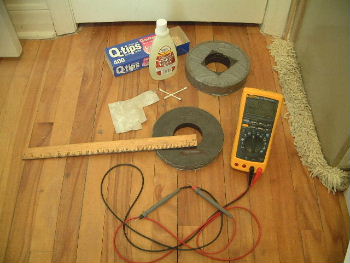
- The following are pictures of the actual top rejection magnets
that David used in his 45GD. He gave them to me to use in my 45GD
but since it doesn't look likely that I'll be building another one
anytime soon, I'll return them. (Note that these details are not
in any of the visits below as I don't recall during which visit he
gave me these. I held off posting information until I did the
Barrium versus Strontium Ferrite tests.)
Top view 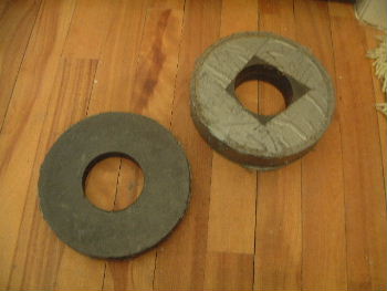
Side view 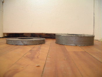
Note that he used three magnets altogether and that all were the same. However, he duct taped two of them together (see pictures above) to act as one. I don't know if the single magnet was used at the top of the top cone or if it was the rejection magnet that was lowered down.
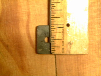
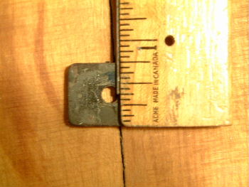
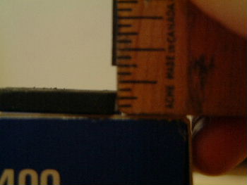
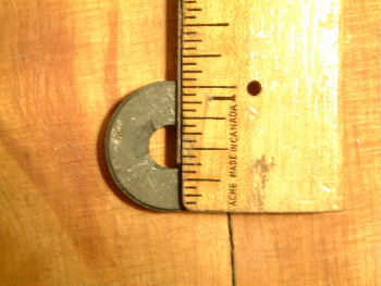
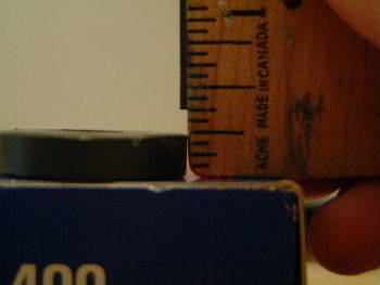
The dimensions are: outer diameter = 7 7/32", inner diameter = 2 15/16", height = 3/4". The following pictures illustrate this.
Outer diameter 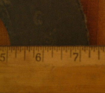
Inner diameter 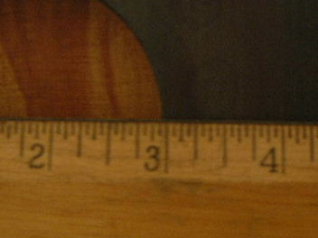
Note the fish-eye effect of this picture makes it look as though the left edge of the ruler doesn't line up whereas it really does if you are looking straight down at it. 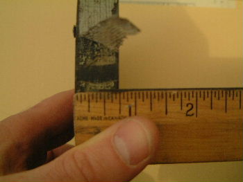
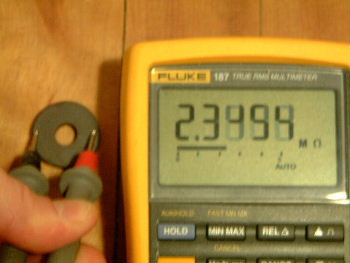
I also wanted to test if the magnets are Barium Ferrite or Strontium Ferrite. I used the testing method described below. These results indicate that these magnets are Barium Ferrite as shown in the following picture.
193.25 Kohms indicate Barium Ferrite. Note that the value was fluctuating but within the range of 190 to 205 Kohms. 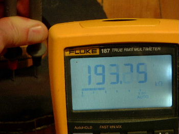
- The drum ring magnets repel the cone rim magnets with like poles facing each other and the opposite poles facing the other direction horizontally, just as in the Bob Thomas drawings. This is something David stressed to me as he had another drawing he was showing me where it was drawn wrongly and wanted me to understand that it was wrong.
- I did ask David about the pole reversal that you see in the Bob Thomas drawing, wherein the top cone's and bottom cone's rim magnets repel the ring magnets with one polarity and the middle cone repels with the other polarity. He said that this is not necessary, but his was an offhand response so I will have to get clarification.
- I asked him about the magnet poles of all the magnets.
He said that they were as follows:
- Top magnets - North facing North
- Top cone rim magnets/opposing magnets - South facing South
- Middle cone rim magnets/opposing magnets - North facing North
- Bottom cone rim magnets/opposing magnets - South facing South
- Osciallator magnets - Attractive (I didn't get details)
- On the drum that I showed David, my drum ring magnets
were taped to an aluminum ring which was in direct contact,
fitting snuggly, with the inner wall of the drum. David
said that this should not be so, otherwise I'd get
electrocuted. I wasn't sure though if that was a cautionary
note based on what happened with his own drum or if that was
how if drum was built.
He said that I should put three pieces of wood down vertically within the drum, on the drum wall, spaced out 120 degrees apart and that the rings should be attached to this wood instead. This seems to be in keeping with what is shown in the Bob Thomas drawing. - I asked for more specs on the spacing between the cone rim magnets and their opposing ring magnets. He said that The spacing when not wobbling was very small, about 1/4 inch. The wobble was also very small, about 1/16 inch. He said that the isotope line barely moved.
- A few people had mentioned that David had embedded the the top magnet in cement which was in turn in a container of some sort. I wanted to verify this with David. He said that he did not do this. He did do the following. The top magnet was a ring magnet. He needed to attach the rod to it so that it could be lowered. So he filled the hole in the ring with cement and put the rod in the cement. That's how he attached the rod to the magnet.
- On David's 45GD, the magnets were inserted into the rim and fixed in place by wrapping tape around the magnets and rim.
- David gave me a few of the actual magnets that he'd used in his
drum. As shown in the pictures below, the dimensions of the
rectangular magnets are: 1"x3/4"x5/32". The dimensions of the
ring magnets are: outer diameter = 1 1/16", inner diameter = 3/8",
thickness = 7/32".
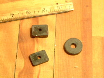
He didn't have single magnets that fit snugly into the bicycle rims. Instead he used stacks of magnets. Starting from closest to the inside of the bicycle ring, he stacked around three rectangular magnets and then one ring magnet. The rectangular ones fit within the rim with the long edge (1") tangential to the curve of the rim. I say there was 'around three' because he showed me using a rim I'd brought, not his. The ring magnet would not fit inside the rim and hence the reason for stacking the smaller rectangular ones inside the rim to fill it in. My camera can't take good pictures of something that small but here are some anyway.
One magnet stack taped into bicycle rim 
Magnet stack - 1" side of rectangular magnet facing camera, ring magnet is on top 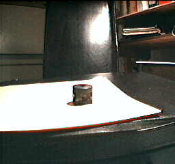
Magnet stack - 3/4" side of rectangular magnets facing camera, ring magnet is on top 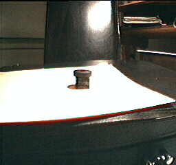
I also wanted to test if the magnets are Barium Ferrite or Strontium Ferrite. I used the testing method described below. These results indicate that both sets of magnets (the rectangular magnets and the ring magnets) are Strontium Ferrite as shown in the following pictures.
This indicates an open circuit (this is the same result you get if you measure the resistance of something that is a nonconductor). 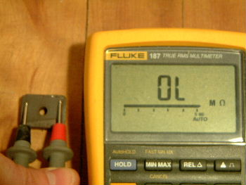
- When I visited him, David had one of those cards you can use to view a magnetic field. It's basically a translucent plastic that is made up of magnetic particles in oil (I think). He was using it to analyse the fields in my magnets. He was checking for continuity. He also mentioned that when the device was working, a third magnetic field becomes visible between the two that are made up from the cone rim magnets and the repelling ring magnets. This third field should appear between their two fields. So if you hold the card flat over the gap between the magnets, you should see three fields when the magnets are pressed close together as they would be during wobbling: one that follows the line of the cone magnets, one that follows the line of the repelling magnets, and one between those two.
Repelling Ring
- On David's 45GD, the repelling ring (the ring with magnets that repel the cone rim magnets) was made out of an aluminum bar formed into a circle.
Drum Construction
- I wanted a clarification on whether on his original drum there was any air gap between the cover and the top of the drum. He said that there was none.
- I asked if there were any holes in the drum. He said no. However, he did suggest putting measuring devices for temperature, pressure and so on in the drum and using some sort of view ports to see them as the cones do their stuff.
Oscillator
- David described the oscillator as in the Bob Thomas drawing, with three balls in triangular form, but David said you didn't need the magnet in the middle. When I showed him mine with the magnet in the middle in attraction, he did not say it was wrong. So the presence of the magnet may be an enhancement and looks to be optional in David's mind. He did specifically ask if mine was in attraction, and when I said yes, he was happy with this.
- As I was not sure from my previous visit, I asked if his oscillator was the type that had the magnet in the middle. He said that it was and that it was attractive.
- The oscillator barely moves, it just vibrates a bit.
Running the Experiment
- I asked David, what liquid did he put in his cones to stabilize them (I'd heard both water and glycerine from others). David said he didn't put any. However, he did say that he put water in the drum so that he could observe the wave motions made by the wobbling cones.
- I told David that my cones were too light to just sit in the magnetic fields and he suggested adding water into the cones to make them the correct weight. (Didn't Pierre Sinclair say that David did this? Funny, when I asked David about this before he said he didn't. I'll have to clarify that someday. Maybe he didn't use this trick himself but was just suggesting it.)
- I asked him how he started it up. Various people asked me to ask him this. He said that all he did was bolt on the lid.
- I asked David if the cones rotate or spin? David said no, they just wobble.
- I asked David what he sat his drum on (bricks, the floor, ...?) He didn't really answer. Instead he said it might be a good idea to put it on rubber or even a tire so that it will be able to vibrate better. (Remember, David didn't have any holes in his drum.)
The following is the same information as above except broken up by date of visit.
August 7, 1999 - visit to David's place
A mutual friend of David Hamel's and mine took me out to visit David. We only stayed for about 3 hours and as it was my first visit, we spent a lot of time just getting to know each other. As a result I was not able to get detailed information on the 45 gallon drum experiment, nor specifically on the construction details of the one he built. That will have to wait for a second visit in a couple of weeks.
However, We did get a little time to go over a drawing he had that someone else had made that he said was incorrect, as well as a drawing that I brought along that was much like the Bob Thomas drawing but with my construction details. I also brought along and showed him what I had built so far. He was delighted to see this and we went over it together briefly (he had to go cook dinner after).
David was working on his large device when I arrived and he gave me a quick tour of it. Amazing to actually see one in person! It was not yet completed but was a far way along. From what I saw, it matches very closely what Dan La Rochelle and Jean-Louis Naudin describe.
The following are the results of my conversations that day with David. Note I asked David if he minded if I post this information and he said, sure, go ahead but that people should wait for Bob Thomas's book as it will have detailed drawings of at least the larger flying craft.
- There are three cones. According to David, two will not do as many people are saying. I got a very clear statement from David on this as I wanted to be sure. I specifically asked if two would do and he said no, and that you need three cones for the isotope line.
- Each cone should be sitting on the cone below it, "halfway" down from that cone's height. This is in keeping with what most people are saying these days. Anything else, David was very clear on this, was wrong.
- Each cone floats, due to the rim/ring magnets' repulsion, and is just barely touching the cone below (or the oscilaltor as in the case of the bottom cone).
- The drum ring magnets repel the cone rim magnets with like poles facing each other and the opposite poles facing the other direction horizontally, just as in the Bob Thomas drawings. This is something David stressed to me as he had another drawing he was showing me where it was drawn wrongly and wanted me to understand that it was wrong.
- I did ask David about the pole reversal that you see in the Bob Thomas drawing, wherein the top cone's and bottom cone's rim magnets repel the ring magnets with one polarity and the middle cone repels with the other polarity. He said that this is not necessary, but his was an offhand response so I will have to get clarification.
- David described the oscillator as in the Bob Thomas drawing, with three balls in triangular form, but David said you didn't need the magnet in the middle. When I showed him mine with the magnet in the middle in attraction, he did not say it was wrong. So the presence of the magnet may be an enhancement and looks to be optional in David's mind. He did specifically ask if mine was in attraction, and when I said yes, he was happy with this.
- I wanted a clarification on whether on his original drum there was any air gap between the cover and the top of the drum. He said that there was none. This is the only statement I have as of this date where he said how something was on his original drum.
- On the drum that I showed David, my drum ring magnets
were taped to an aluminum ring which was in direct contact,
fitting snuggly, with the inner wall of the drum. David
said that this should not be so, otherwise I'd get
electrocuted. I wasn't sure though if that was a cautionary
note based on what happened with his own drum or if that was
how if drum was built.
He said that I should put three pieces of wood down vertically within the drum, on the drum wall, spaced out 120 degrees apart and that the rings should be attached to this wood instead. This seems to be in keeping with what is shown in the Bob Thomas drawing.
October 23, 1999 - visit to David's place
Visited David again with our mutual friend. David now has the second cone of his saucer put on top of the first cone and is starting on the third cone.
I again brought my 45 gallon drum along with a short list of questions. The following are the results of our conversation regarding the drum.
- I asked for more specs on the spacing between the cone rim magnets and their opposing ring magnets. He said that The spacing when not wobbling was very small, about 1/4 inch. The wobble was also very small, about 1/16 inch. He said that the isotope line barely moved.
- A few people had mentioned that David had embedded the the top magnet in cement which was in turn in a container of some sort. I wanted to verify this with David. He said that he did not do this. He did do the following. The top magnet was a ring magnet. He needed to attach the rod to it so that it could be lowered. So he filled the hole in the ring with cement and put the rod in the cement. That's how he attached the rod to the magnet.
- I asked David, what liquid did he put in his cones to stabilize them (I'd heard both water and glycerine from others). David said he didn't put any. However, he did say that he put water in the drum so that he could observe the wave motions made by the wobbling cones.
- I asked David if the cones rotate or spin? David said no, they just wobble.
- I asked him how he started it up. Various people asked me to ask him this. He said that all he did was bolt on the lid.
- I asked if there were any holes in the drum. He said no. However, he did suggest putting measuring devices for temperature, pressure and so on in the drum and using some sort of view ports to see them as the cones do their stuff.
- I asked if the cones were all the same diameter. He said yes, they were all the same diameter.
- I asked if it was okay if the top cone had a closed top (as in Justin's design). He said yes, that was okay.
- As I was not sure from my previous visit, I asked if his oscillator was the type that had the magnet in the middle. He said that it was and that it was attractive.
- I asked him about the magnet poles of all the magnets.
He said that they were as follows:
- Top magnets - North facing North
- Top cone rim magnets/opposing magnets - South facing South
- Middle cone rim magnets/opposing magnets - North facing North
- Bottom cone rim magnets/opposing magnets - South facing South
- Osciallator magnets - Attractive (I didn't get details)
February 13, 2000 - phone call
- He used ordinary bicycle rims, not aluminum (NOTE THAT ON MY JUNE 29, 2000 VISIT, THIS TURNED OUT TO BE WRONG). He took the spokes out. The magnets fit in perfectly. He did not put any lining in between the magnets and the rim.
May 8, 2000 - phone call
- His top magnets (top rejection magnet and top cone magnet) were od=6", id=4". (Note, these dimensions turned out to be wrong once he gave me the actual magnets that he used. See the section on Magnets above. I guess he was just giving me rough figures.) When they are 3 or 4 inches apart they will begin to repel.
June 29, 2000 - visit to David's place
Visited David again with our mutual friend. David now has the base cone on a stand outdoors and the middle two cones (the ones that will be floating) are more or less complete. Only parts of the top cone have been made so far. He is now working on the rings that have the rejection magnets.
I again brought my 45 gallon drum along with a short list of questions. The following are the results of our conversation regarding the drum both during the visit and from a follow-up conversation. You won't like some of the information as it is different than what is commonly understood to be the case. One example is that he used aluminum bicycle wheels instead of steel - so that they don't affect the magnetic fields. Much of the other material confirms what we already know.
I called to double check that his 45GD used aluminum bicycle rims and he said yes. I can see where there was some confusion though. I started out by asking if "he used steel bicycle rims" and he said yes. Then, knowing that he has a lot of bicycle rims now and uses them as construction aids, I pressed him further - "on your 45GD that exploded, did you use aluminum or steel bicycle rims" and he said aluminum. (Note that he later said steel when Dan LaRochelle and I were both there and questioning him. :-()
- On David's 45GD, the repelling ring (the ring with magnets that repel the cone rim magnets) was made out of an aluminum bar formed into a circle.
- On David's 45GD, the bicycle rim was aluminum so that it did not affect the magnetic field.
- On David's 45GD, the magnets were inserted into the rim and fixed in place by wrapping tape around the magnets and rim.
- David gave me a few of the actual magnets that he'd used in his
drum. As shown in the pictures below, the dimensions of the
rectangular magnets are: 1"x3/4"x5/32". The dimensions of the
ring magnets are: outer diameter = 1 1/16", inner diameter = 3/8",
thickness = 7/32".
He didn't have single magnets that fit snugly into the bicycle rims. Instead he used stacks of magnets. Starting from closest to the inside of the bicycle ring, he stacked around three rectangular magnets and then one ring magnet. The rectangular ones fit within the rim with the long edge (1") tangential to the curve of the rim. I say there was 'around three' because he showed me using a rim I'd brought, not his. The ring magnet would not fit inside the rim and hence the reason for stacking the smaller rectangular ones inside the rim to fill it in. My camera can't take good pictures of something that small but here are some anyway.
One magnet stack taped into bicycle rim Magnet stack - 1" side of rectangular magnet facing camera, ring magnet is on top Magnet stack - 3/4" side of rectangular magnets facing camera, ring magnet is on top I also wanted to test if the magnets are Barium Ferrite or Strontium Ferrite. I used the testing method described below. These results indicate that both sets of magnets (the rectangular magnets and the ring magnets) are Strontium Ferrite as shown in the following pictures.
This indicates an open circuit (this is the same result you get if you measure the resistance of something that is a nonconductor). - On David's 45GD, he didn't have any supporting frame in the cones.
- On David's 45GD, each of the three cones was actually made up of two cone skins, an outer full height cone skin and an inner cone skin that was made such that the cone above it would sit halfway down the cone below it.
- On David's 45GD, the cone skins were riveted to the bicycle rim. Just where this was done doesn't matter.
- On David's 45GD, there was no nail for the point at the bottom of the cone. Instead the cone skin was formed to a point.
- I told David that my cones were too light to just sit in the magnetic fields and he suggested adding water into the cones to make them the correct weight. (Didn't Pierre Sinclair say that David did this? Funny, when I asked David about this before he said he didn't. I'll have to clarify that someday.)
- The oscillator barely moves, it just vibrates a bit.
- I asked David what he sat his drum on (bricks, the floor, ...?) He didn't really answer. Instead he said it might be a good idea to put it on rubber or even a tire so that it will be able to vibrate better. (Remember, David didn't have any holes in his drum.)
- The cones skins are very important for moving/torquing the air.
- The cones are what make the invisible (air) become visible (the air becomes plasma). (So that's what he means by invisible and visible!)
- When I visited him, David had one of those cards you can use to view a magnetic field. It's basically a translucent plastic that is made up of magnetic particles in oil (I think). He was using it to analyse the fields in my magnets. He was checking for continuity. He also mentioned that when the device was working, a third magnetic field becomes visible between the two that are made up from the cone rim magnets and the repelling ring magnets. This third field should appear between their two fields. So if you hold the card flat over the gap between the magnets, you should see three fields when the magnets are pressed close together as they would be during wobbling: one that follows the line of the cone magnets, one that follows the line of the repelling magnets, and one between those two.
Testing for Barium Ferrite or Strontium Ferrite
To test whether a magnet is Barium Ferrite of Strontium Ferrite you first sand about 1 inch length of the magnet using fine sandpaper. Then swab some acetone (nail polish remover contains acetone) on the areas where the DMM (Digital Multimeter) probe tips will be placed. Then measure the resistance using a DMM across this 1 inch area, pressing down hard with the probes.
It is Barium Ferrite if the resistance is between 10 KOhm and 200 Kohm (approximately). It is Strontium Ferrite if the resistance is above 0.5 Mohm and will often read as an open circuit (1000 Mohm or more).
|