This was my first attempt at building this device. When I began
construction of it, accurate details on how it should be built
were very scanty and there was much incorrect information
floating around. Since then I have visited David in person
and have talked to others who also have had contact with David
and the information content is much better, hence my newer versions.
This version was not a success though much about the construction
issues was learned.
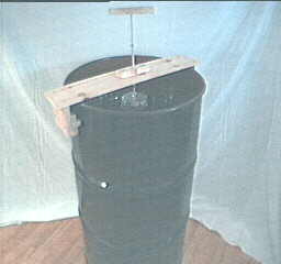
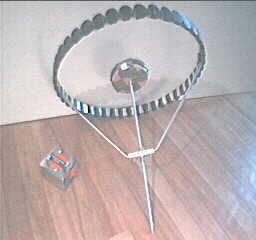
The Device
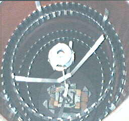
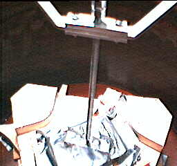
Full front view of 45 gallon drum experiment.
Note the plunger mount and plunger sitting on top of the drum.
Normally the plunger mount would be clamped onto the rim of the drum.
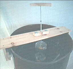
Close up showing the plunger lowered into the drum.
The top cone's center magnet can be seen below the plunger magnet.
They repel each other.
Even better view of plunger and top cone's magnet.
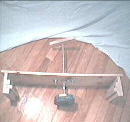
Plunger mount and plunger.
Top cone, without skin. The measuring tape is for scale.
Top cone, closeup, showing construction details.
Bottom cone without skin.
Bottom cone. Closeup showing details of notch which top cone sits in.
The notch was drilled and carved into the top of the screw, then
2 hex nuts were added, the top nut providing extra security in case the
top cone decides to jump up out of the notch.
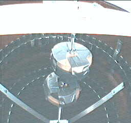
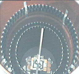
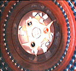
Looking down inside of drum -
Plunger mount and plunger have been removed for better view.
Notice the gap between the cones' rim magnets and the rings of
magnets on the drum wall. The rings of magnets on the wall repel
the magnets on the rims of the cones. This holds the cones centered
but also allows them to wobble when downward/sideways pressure is
put on the top cone's center magnet by use of the plunger.
Note that the bottom piece on which the bottom cone sits has been
replaced by an oscillator.
Looking down inside of drum -
Top cone has been removed so that bottom cone is more visible.
Note that the bottom piece on which the bottom cone sits has been
replaced by an oscillator.
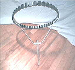
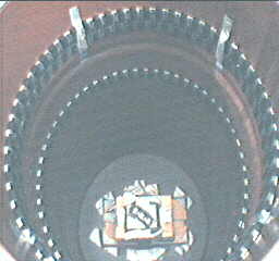
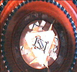
Looking down inside of drum -
All cones removed for better view of drum interior.
Note that this picture is a little out of date as the complicated
looking thing at the bottom has been replaced with an oscillator.
This complicated looking thing is simply a stack
of conviently sized wood, duct taped together to get the proper
height. On the top center of all this wood is a piece of aluminum
with a notch cut into it.
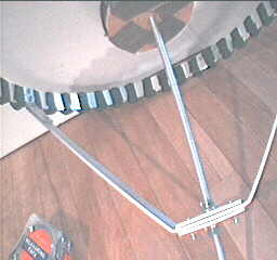
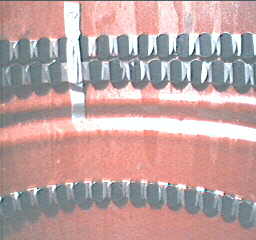
Closeup of rings of magnets in drum.
The top two rings repel the top cone's rim magnets. The bottom
ring repels the bottom cone's rim magnets.
(the drum has two grooves in it, one of them is visible between
the top rings and the bottom ring).
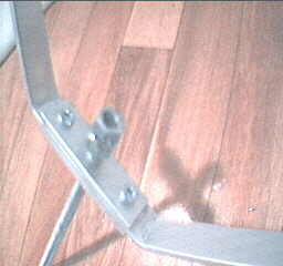
Closeup inside drum where point of bottom cone
sits in notch. This picture is up to date as the notch is actually
a part of the oscialltor.
View inside drum of bottom plate of
oscillator -
The pool balls are visible in the three corners.
View inside drum of complete
oscillator -
The rectangle at the center is the piece of aluminum with the
notch. It is this notch which the bottom cone sits in.
Conclusion
At this scale, it seems fairly easy to make a cone stand
upright on a point.
Problems
- The top cone is sitting on the bottom cone. If the top cone
tilts and the bottom cone does not tilt then the rim of the
top cone will meet the drum ring magnets at some height X.
If the top cone tilts and the bottom cone tilts then the rim
of the top cone will meet the drum ring magnets lower down
than X, say at height Y. What this means is that the top cone's
rim has quite a range of height wherein it can meet the drum
ring magnets.
One thing I have tried so far is to increase the number of
rings on the drum wall for the top cone. That is why you see
two rings for the top cone in the pictures above. This works
a little but is not good enough. One reason it is not good
enough is because I am using ring magnets. The faces
of the rings magnets are repulsive but the gaps between the
ring magnets are attractive (see the picture above)! So
sometimes, when the top cone tilts, it'll actually touch
these gaps. It'd probably be better if I had a bunch of
tall rectangular magnets instead so that there would be no
gaps and no need of multiple rings. Another reason that my
two rings are not good enough is that I really need three
rings - the range of possible contact heights is that great.
- When the top cone wobbles, it doesn't make the bottom cone
wobble very well. Instead, the bottom cone sits stationary
while the top cone wobbles away.
This wobbling has already been improved from the first
attempts by making the tips of the cones more pointy - thanks
to input from Leon Canning.