
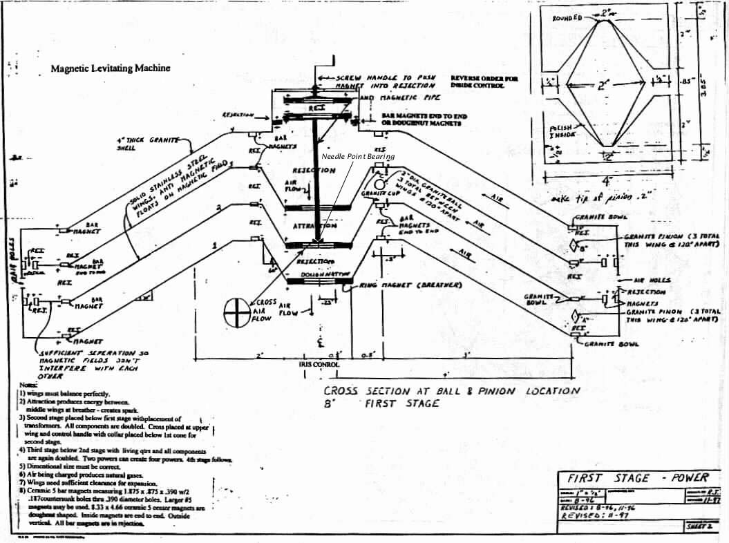
The complete ship is actually built as three stages. The first stage is usually refered to as the motor and is what most of this page details. At the bottom are a few pictures dealing with the second stage. All magnets are ceramic magnets.
Before my first contact with David Hamel I tried to build my own smaller and cheaper version of the motor component (first stage) by roughly following Pierre Sinclaire's blueprints.
Everything that I write here will have been told to me by David Hamel. I will try very hard to make sure that nothing is invented by me.
First Stage
The first stage is analagous to the ionoshere as it is in that stage that the ions are produced. The second stage is analagous to the stratosphere since the air within this stage is thin and it is hard to breath. The third stage is analagous to sea level and that is where the passengers will live. The previous motor that David had built that flew away was equivalent to the first stage (or motor).
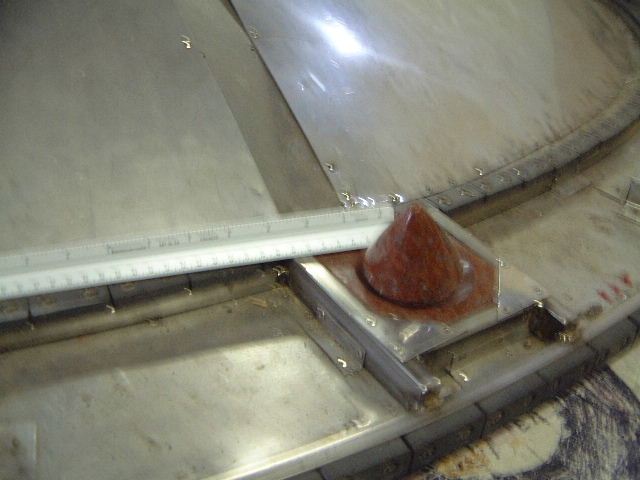
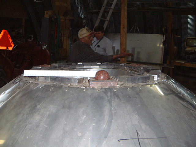
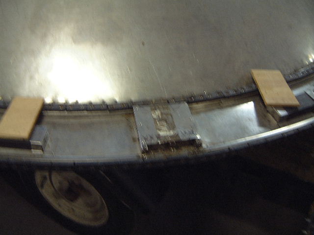
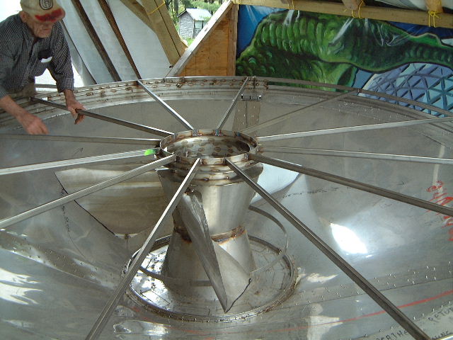
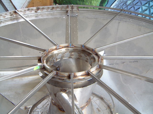
The motor consists of a top, two semi-free floating wings and a base. The top and the base are fixed in place. The wings are floating on and are somewhat restricted by ceramic magnets but are also restricted in how far they can move through the use of balls and pinions. As you can see by the diagram there are three granite balls spaced 120 degrees apart between the two wings. A picture of one of the balls can also be found below. There are six granite pinions altogether spaced 120 degrees apart. There are three pinions between the top and the top wing and there are three pinions between the base and the bottom wing. See the diagram and pictures below for more on the pinions.
|
|
|
Some additional drawings, photos of David's construction and photo's of Tracy Jone's efforts can be found here. (look for links labeled HFS or Hamel Flying Saucer).
Click on the small images to see larger versions.
|
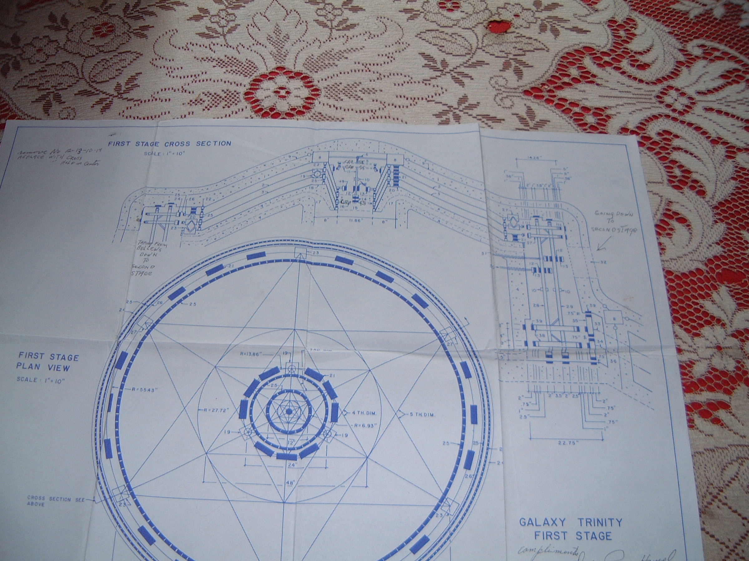
Blueprint drawn by Bob Thomas of the first stage and part of the second |
Rejection magnets

|
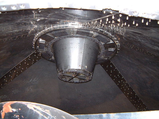
David is holding the ceramic magnet and rod that are at the top of the motor. There are actually two magnets in this picture, the first is the one that is attached to the rod and the second one is the one that will be lowered down to repel the first one. |
Top of motor

|
Closeup looking down of the cone that will be a part of the top. |
|
Side view of the cone that will be a part of the top. |
Top wing (i.e. first wing from the top)
|
This is a view looking down into the cone of the top wing. The raised square piece houses the cup for the ball that will be between the two wings. The ball can be seen sitting in the cup belonging to the bottom wing in a picture below. |
|
A view of a pinion sitting in its cup in the rim of the top wing. |
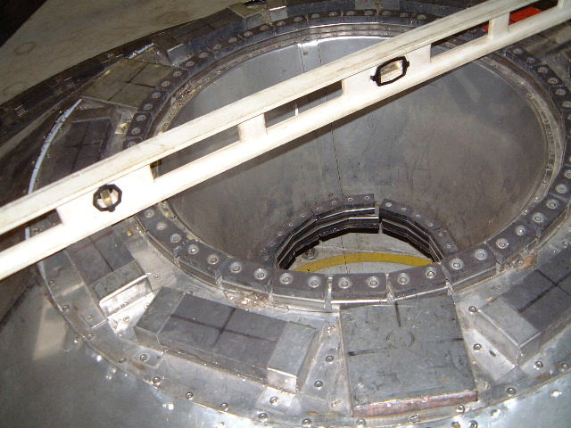
Bottom wing (i.e. second wing from the top)
|
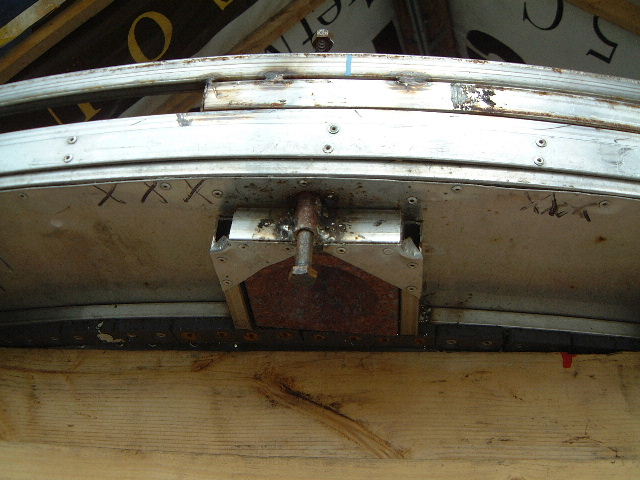
This is looking up underneath the bottom wing. The cross can be seen at the bottom of the cone. This is what the rod in the picture above will be sitting in and moving. |
|
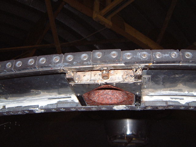
This shows a ball sitting in its cup. This ball will restrict the movement of the wings with respeect to each other. In the background David can be seen explaining something to Ole. |
|
A view of the housing for the cup for a pinion. The next picture shows the same thing from underneath. The pieces of wood are temporary and are for when the top wing is lowered on this one for testing. |
|
The cup for a pinion. |
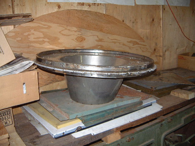
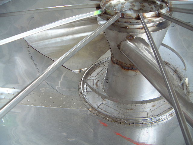
Base
Note that on this day the base was sitting upside down outside so keep that in mind as you look through these pictures.
|
The base sitting upside down outside. |
|
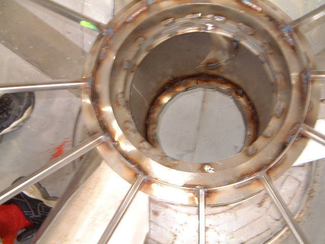
The underside of the base. It is through the center hole that you see that the air returns. Dan LaRochelle refers to this is as the "1st Stage Vortex Return". |

|
If you look closely in the circular hole you can see another crescent shaped hole. It looks like the winglike shapes channel the air into this central column. I could speculate more but I said I wouldn't add things that David didn't tell me. |

|
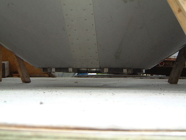
Just below David's right hand you can see a horizontal slit in the circumference of the rim of the base. There are three of these around the circumference and David said they are air intakes. Yet more pictures below... |
|
|
|
A shot of a hole with a bolt in it. If you look back at the pictures of the bottom wing pinions you will also see holes in the same places. When the wings are being placed on top of each other, a bolt will be put through these holes to hold them lined up over each other. |
|
This is the same hole that is in the previous picture. Note the cup for the pinion. Remember, the base is upside down in these pictures and this shot is looking upwards. The pinion in question is the one that will be restricting of the bottom wing which will be floating above the base. |
|
Looking more directly down the central hole of the base. Or more precisely, looking up the cenral hole (since the base is sitting upside down in these pictures). Note the crescent shaped hole in the side for admitting air. |
|
I should have turned my camera upside down. This is a picture of the top of the base. |
|
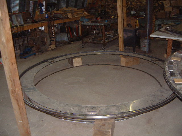
Sitting on the floor is the rim that still needs to be attached to the base as well as a ring of ceramic magnets for repelling one of the two wings' rim-magnets. |
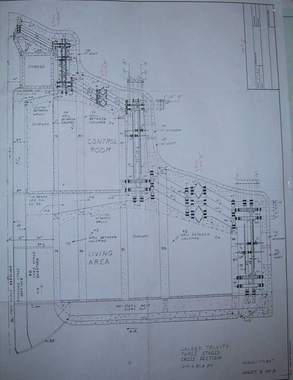
Second Stage
|
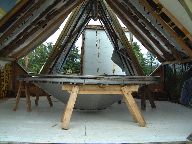
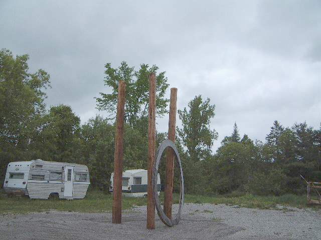
Once the motor is complete, work begins on the second stage. The entire ship is being built from the top down, the motor being at the top. So the motor will sit at the top of these three poles while the second stage is built down from there. |
|
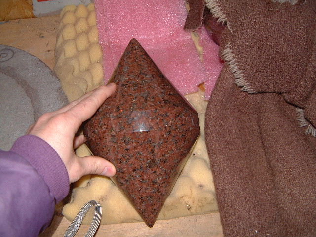
This is one of the pinions for the second stage. Note that following the rules of the dimensions as David refers to it or the master pyramid matrix as many others refer to it, this pinion is larger than the ones in the first stage. |
