
The objective of this is to test the use of the high K dielectric, polysulfide, in conjunction with the Biefeld-Brown effect. According to T.T. Brown, the higher the K of dielectric between the electrodes, the stronger the Biefeld-Brown effect.
This design was copied from that of the ANGEL project of James Batchelor. Note that the one detailed below doesn't work most likely due to the sealant used as a dielectric containing some conducting material.
Be careful when working with sealants. Some contain toxic materials.
Be sure and take the necessary safety precautions such as the proper
mask, gloves and goggles. Work in a well ventilated area.
The following diagram shows the design of the device itself. Note that in the Mark 1, the brass wire was buried just within the surface of the sealant, unlike in the diagram. In the Mark 1B, the brass wire was in air in front of the sealant more like the diagram below but at adjustable distances.
|
The device consists of two electrodes, one of aluminum foil and the other being a brass wire. The two are seperated by a large quantity of polysulfide. The polysulfide is really a polysulfide based sealant called Deck-O-Seal which is normally used as liquid plastic filler for cement joints around swimming pools. Polysulfide reportedly has an incredible dielectric constant of 2260. NOTE THAT THIS PARTICULAR SEALANT MAY CONTAIN CONDUCTING MATERIAL AND SO IS NOT A GOOD ONE TO USE.
The High K Mark 1
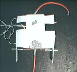
The following are pictures of the completed High K Mark 1 device. Notice that I've buried the brass wire in the polysulfide instead of leaving it exposed as in the above diagram.
|
|
|
Experiments and Results
Tried the High K Mark 1, both from a tower that permitted it to pull a rotor around in a circle and pointing updwards sitting on a digital scale. I tried with both polarities in both tests (i.e. positive on wire and negative on wire). I used this high voltage power supply.
In all cases there was no measurable force. Mostly there was no sound but sometimes there was a very quiet hissing. Also, when discharging the power supply there was no arcing. This leads me to believe that the elecrodes were conducting through the sealant (i.e. that the sealant contains some conducting material).
The High K Mark 1B
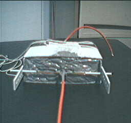
To get around the problem of the sealant conducting, I decided to put an air gap between the sealant and the brass wire. The following are pictures of the High K Mark 1B (the slightly modified Mark 1).
|
|
Experiments and Results
Tried the High K Mark 1B from a tower that permitted it to pull a rotor around in a circle. I tried with both polarities (i.e. positive on wire and negative on wire). I used this high voltage power supply. I tried with a .25" sealant/wire gap and with a 1.25" sealant/wire gap.
In the case of the .25" gap, there was no movement but there was loud hissing and a purple corona in the gap.
In the case of the 1.25" gap, there was a very slow movement with distinctive purple corona jets between the wire and the sealant. The movement was mostly likely caused by ion wind. This is to be expected as the sealant was likely acting as a conductor.
Conclusion
I need to get a polysulfide based sealant the does not contain any conducting material.
Construction
Firstly a mold was made out of white plastic sheets. A hole was drilled into the back of the mold to admit a wire. One end of the wire was attached to the back (or middle) of the aluminum foil, the other being left for connecting to the power source. The polysulfide was then injected into the mold in 3 layers. The first layer was the layer beneath the aluminum foil (i.e. sitting on the bottom of the mold). The second layer was that which filled the inside curve of the aluminum foil. And the third layer was the layer on top of the aluminum foil. The following picture illustrates this a little.
|
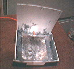
This particular sealant normally takes 8 hours just for a skin to form. This is the reason that it was done in layers, each layer gets a better chance to dry. The three layers mentioned above were injected about 8 hours apart.
