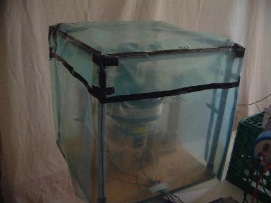
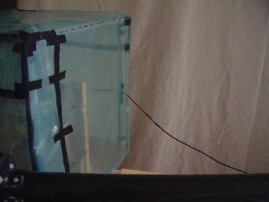
The test stand under a polyethylene bottomless cover.
I was going to tape the bottom of the cover to the base of the test stand
so that air could neither go in or out but there was no weight change
during testing so air-in was probably equal to air-out in effect. Either
that or air flow was kept inside.
 |
|
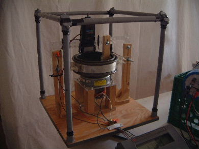
Without the cover.
 |
|
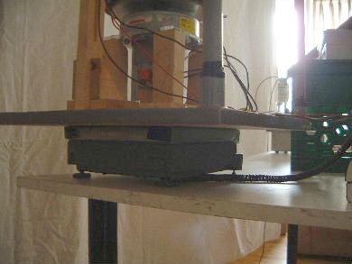
The digital scale under the test stand.
 |
|
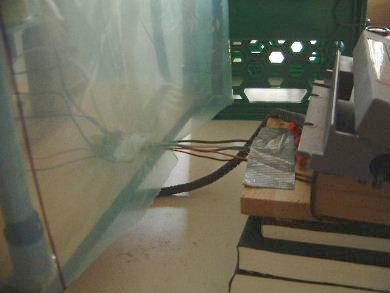
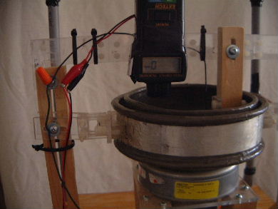
The various wires (motor power, ground, phototachometer
power). Given that putting on a light playing card showed full weight
change, the wires had no effect on weight change.
 |
|
The high voltage wire.
 |
|
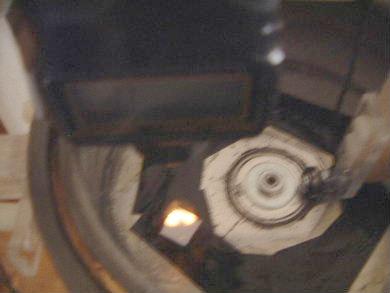
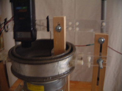
The phototachometer looking down into the
rotating cylinder to show how it measures speed. A light is shone down
and reflects off the shiny square.
 |
|
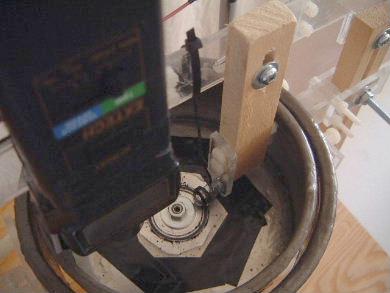
I wanted to make sure that the rotating cylinder
stayed grounded. Near the center of the cylinder you can see a
bearing,
supported by the wood and acrylic piece sticking down. The bearing
contains conductive grease and has a wire from it to ground.
The black ring on the cylinder bottom is conductive grease that has
come out of the bearing.
 |
|
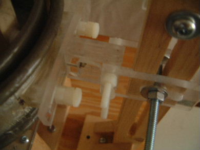
View of one side of the support. Note the
adjustability. It was needed so that the stationary cylinder could
be centered properly.
 |
|
View of the other side of the support.
 |
|
Showing the adjustable parts. Note that the
stationary cylinder is high voltage with respect to ground so everything
is made of acrylic and nylon.
 |
|

