|
|
|
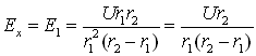
Are cylindrical and spherical E-field thrusters violating Newtons 3rd law?
disproved analysis based on the classical model
The following demonstration was the first attempt to analyze the electrostatic forces in cylindrical coaxial- and spherical capacitors with two different dielectrics between the electrodes, based on the classical understanding and accepted basic correlations. The measurements however, disproved the results of this analysis, and it is presented here only to demonstrate the consequences of the classical model that leads to contradiction and wrong results. The related measurements and the correct analysis with newly discovered laws are presented on the page
semicharge.htm . Please note again that the analysis below is not correct because the basic F=qE formula is not applicable here!
Previously we have discussed the force components of the electrostatic pressure acting on the surface of the conductive electrodes. However, in the presence of dielectrics two additional dielectrophoretic force components appear that act on the dielectric material. One of these dielectrophoretic force components that appear at the edges of the capacitor due to arced, inhomogeneous E-field lines has been discussed under dielectrophoretic pumps and we can call them edge-effect (EE) forces. The other dielectrophoretic force component will be described below.
In fig. 5a. of the tutorial page about dielectrics it is shown that a dielectrophoretic force will attract the elementary dipoles of the dielectrics molecules towards the greater E-field intensity. The shape of the E-field between the electrodes of semi-cylindrical and hemispherical thrusters is inhomogeneous and converging towards the smaller electrode, where it reaches its maximum. Consequently the mentioned dielectrophoretic force will push the molecules of the dielectric towards the higher E-field intensity i.e. towards the smaller electrode. To differentiate this force component from the earlier discussed edge-effect force we can call it convergent-field effect (CFE) force, although basically both types are dielectrophoretic forces.
CFE force of the semi-cylindrical thruster
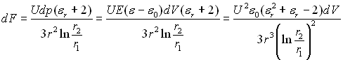
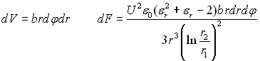
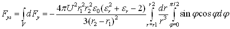
Let us calculate the magnitude of the resultant force component in the y direction, originating from these dielectrophoretic forces acting on the dielectric only between the electrodes. To accomplish this task we will have to know the attracting and repelling Coulomb forces upon the positive and negative charges of the elementary dipoles. Then by summing up these two opposing forces we get the resultant force upon the dipole. By integrating the elementary force components in the y direction over the whole volume of the dielectric, the macroscopic resultant force will be obtained. To perform these calculations, we have to know the magnitude of the equivalent dipole dp of an infinitesimal volume of polarized dielectric dV as the function of the local E-field intensity. In the case of linear isotropic dielectrics this is calculated as below:
The electric polarization represents the density of dipoles per volume
![]() (where: n number of dipoles; V volume; N density
of dipoles; p- elementary dipole). We get the correlation between
P and E as:
(where: n number of dipoles; V volume; N density
of dipoles; p- elementary dipole). We get the correlation between
P and E as: ![]()
The dipole moment of an infinitesimal volume of dielectric is:
![]()
Now we can calculate the resultant Coulomb force upon a dipole (fig. 10).
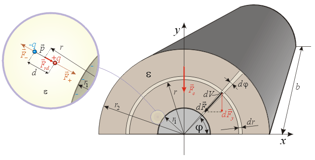
Fig. 10.
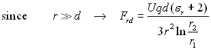
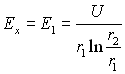
The E-field intensity between the electrodes of a cylindrical capacitor
is: 
However this represents the total E-field at a certain point within the dielectric that is the sum of the E-field component created by the examined dipole (molecule) and the E-field components created by all the other dipoles (molecules) and free charges farther away from the examined dipole. If we want to calculate the Coulomb forces upon the examined dipole at this point with the formula F=qEeff (according to the established scientific understanding) then the effective E-field intensity in this formula should not include the self-generated E-field component originating from the examined dipole, but only the E-field component created by all the other E-field sources. The formula for the wanted effective polarizing E-field is:
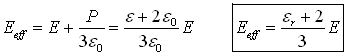
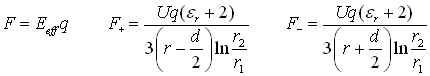
The derivation of this formula can be found in standard electromagnetic textbooks and we will not discuss it here. When calculating the Coulomb forces upon the positive and negative charges of the examined elementary dipole we will use Eeff instead of E. The attracting and repelling forces upon the opposite charges of the dipole are:
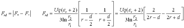
The resultant force upon the dipole is:
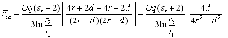
Using the definition of the dipole:
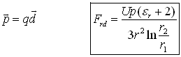
As the next step, knowing the equivalent dipole moment of an infinitesimal volume of polarized dielectric dp, and the resultant force upon such a dipole attracting it towards the smaller electrode:
The y component of this force (fig. 10)
is: ![]()
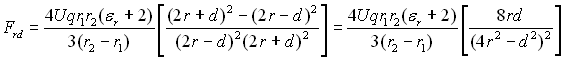
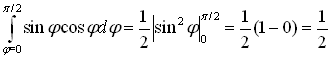
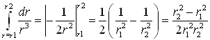
By integrating these force components acting upon the infinitesimal volumes over the whole volume between the electrodes filled with dielectric (fig.10), we get the resultant macroscopic force in the y direction that we were looking for:
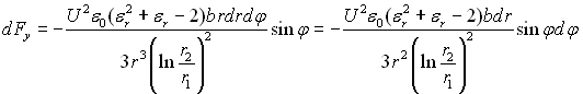
Introducing a temporary constant:
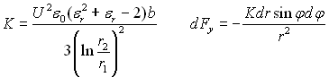
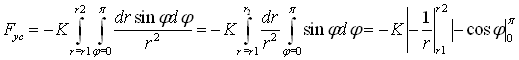
The negative sign means that the resultant force points towards the negative y direction (towards the smaller electrode).
CFE force of the hemispherical thruster
The method of calculation (fig. 11) is the same as for the semi-cylindrical thruster.
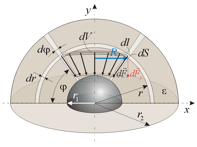
Fig. 11.
The E-field intensity between the electrodes is: 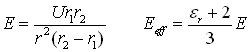
The attracting and repelling forces upon a dipole are calculated similarly as illustrated in fig. 10:
The resultant force upon a dipole is: ![]()
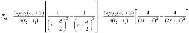
Substituting 
Using the previously derived correlation ![]() we can
calculate the force upon an infinitesimal volume of dielectric:
we can
calculate the force upon an infinitesimal volume of dielectric:

The infinitesimal volume is calculated as:
![]()
![]()
Substituting this into correlation (1):

The y component of this force is ![]() thus the
resultant macroscopic force on the dielectric between the electrodes in
the y direction is:
thus the
resultant macroscopic force on the dielectric between the electrodes in
the y direction is:
Solving the integrals first:
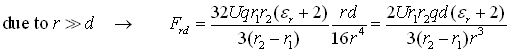
The final formula of the thrust is:


The negative sign shows that the force is pointing towards the negative y direction.
In the case of an open semi-cylindrical and semispherical thrusters there are four main force components that make up the resultant thrust of the device. Up till now we have derived the formulas for the following three components:
- the electrostatic pressure (EP) component between the electrodes, that tends to pull the surface charges out from the surface of the conductive electrodes,
- the converging field-effect (CFE) component between the electrodes, that is a dielectrophoretic force upon the molecules of the dielectric due to inhomogeneous E-field,
- the edge-effect (EE) component at the bottom edge of the semi-cylindrical or hemispherical thruster, which is also a dielectrophoretic force upon the dielectric due to the arced and inhomogeneous E-field, tending to push the dielectric from outside the edges into the thruster capacitor (between the plates).
The fourth and yet unknown component is also an EP component acting on the bottom edges and the outside surface of the electrodes. Due to the complex E-field shape in this region this cannot be calculated analytically, but a numerical method should be used.
The practical concept of reaction-less force and Newtons 3rd law
Before starting the description we should clarify briefly the issue, what does the violation of Newtons 3rd law mean, and define the concept of reaction-less force. According to our everyday experiences, forces are exerted upon a body either by physical matter through direct mechanical contact, or by force fields that are originating also from physical matter. Thus the force-field acts as a mediator medium between the two bodies made of physical matter and it develops an action and reaction in distance, but the forces seem to be the same as if the bodies would act upon each other through direct mechanical contact.
Newtons 3rd law declares that if a physical body acts upon a second physical body with force a F then the second body will also act upon the first body with a force of same magnitude but opposite direction F. That means, if there is an active force tending to accelerate a body then there must also exist another reaction force of same magnitude and opposite direction acting on a second body, and there cannot exist an active force without a reaction force.
If there would be such force then we could call it a reaction-less force, since it does not require any reaction force, or the presence of a second body (to react) in order to be active and accelerate a physical body. According to this interpretation if we measure a unidirectional electrostatic force (developed by the E-field) upon a thruster, we can call it reaction-less since it does not develop any reaction force upon physical matter and it does not require the existence of a second physical body in order to be active and be able to accelerate the thruster. This active force is originating from the electric force field and thus we might expect that consequently the reaction force should be transferred to the physical matter that creates this field (to electric charges, and from them to the atoms of a body); the law of action-reaction between physical bodies should still remain valid. However, in the case of E-field thrusters the sources of the accelerating E-field are the same charges that are present on the surface of the electrodes and the reaction force would act on these charges counteracting the active accelerating force. Thus no resultant thrust would exist on a thruster without the presence of external force fields and physical bodies. If we still prove that a resultant unidirectional thrust can exist upon a thruster that does not originates from external medium then it is justified to call it reaction-less since from a physical and practical point of view the reaction force does not manifest in the perceived rough physical dimension.
The force fields are special manifestations, energetic states of the background ether, and they are part of the ether sea in which all matter flows. Thus they can lean upon this subtle fluid substance that represents a reaction background to interact with physical matter. Now we could say that we have found the reaction background and the law of action-reaction is still valid, since the force-field (i.e. the ether) bears the reaction force that should have the same magnitude as the action force upon the thruster. However, the substance of the reaction background (the ether) belongs to a more subtle dimension, and it is not a rough physical matter that would have the same characteristics as the well known physical matter. Therefore from practical point of view we can still call the discussed thrust reaction-less within the rough physical dimension (or frame of reference) to differentiate it from the usual forces that always invoke a reaction force upon physical bodies.
The asymmetric cylindrical and spherical thrusters seemingly violate Newtons 3rd law
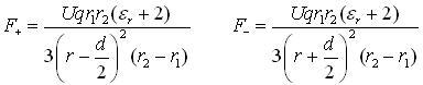
In order to develop a unidirectional reaction-less thrust we have to create an asymmetry of the electrostatic forces acting upon a capacitor. This asymmetry has been achieved in the case of open semi-cylindrical and hemispherical thrusters so that one half of the cylinder or sphere has been removed. However, this created open edges and an E-field on the outer surface of the electrodes that is complex and hard to calculate. Thus let us take first the easily calculable shape of straight E-field lines between the electrodes of a cylindrical or spherical capacitor, and try to create an asymmetry in the forces by an asymmetrical dielectric configuration. This is easily achievable if we take two semi-cylindrical (or hemispherical) capacitors of same size, filled with dielectrics of different permittivity, and join their open sides getting a full cylindrical (or spherical) capacitor filled with 2 different dielectrics. In other words we can just take a complete cylindrical capacitor and fill (the cross-sectional) one half of the space between electrodes with one dielectric and the other half with another dielectric (fig. 12).
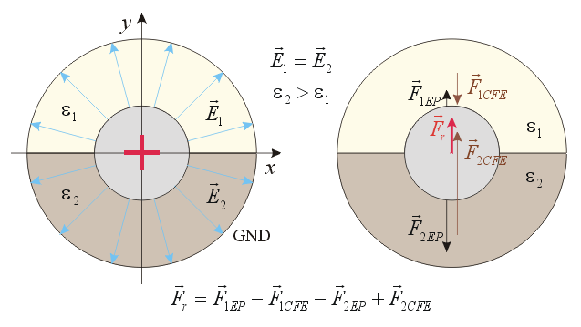
Fig. 12.
In this case there are no free edges, thus the edge-effect forces have been eliminated. When there are equal quantities of opposite charges on the two electrodes, there is no E-field outside the thruster nor inside the smaller electrode but the whole E-field is confined between the two electrodes (ignoring the limited stray E-field at the ends). Thus there are no forces on the outside of the thruster nor on the inside of the smaller electrode. There are only 2 force components for both segments of the thruster (thus a total of 4). We have already derived the formulas for both components:
- the EP component developed by the surface charges on the electrodes and
-
the CFE component pushing the dielectric towards the smaller electrode.
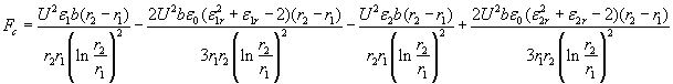
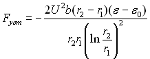
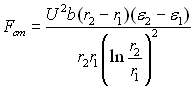
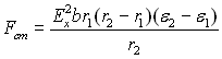
Cylindrical thruster:
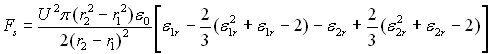
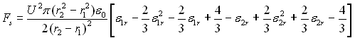
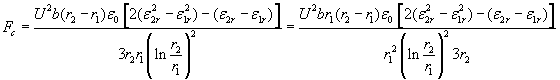
The resultant thrust of the full cylindrical thruster with two segments of identical size filled with 2 dielectrics of different permittivity is calculated as:
![]()
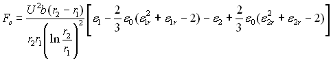
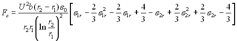
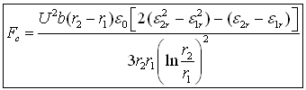
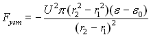
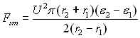
Spherical thruster:
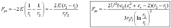
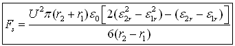
When the above-described thruster has spherical shape instead of cylindrical, the resultant thrust will be:
![]()
![]()

These results predict that a non-zero resultant unidirectional reaction-less thrust can be obtained from the examined thrusters if high voltage is applied to the electrodes. The direction of the resultant thrust is pointing towards the segment of lower dielectric constant (fig. 12).
Analyzing the results
Diagram 3 shows the dependence of these forces upon the radius of the smaller electrode and uses the following parameters: r2=1cm; er1=2; er2=4; l=2r2; U=30 kV.
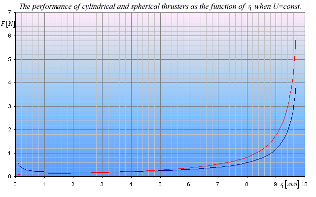
Diagram 3.
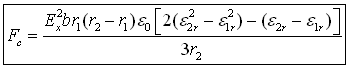
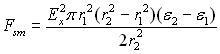
The above diagram shows intense forces when the distance between electrodes is very small. However, this is due to very intense E-fields reaching above the limit of the dielectric strength, so the principle that the performance is increased by decreasing the distance between the electrodes as much as possible shown by the diagram can be applied only up to a certain limit. It can be used as long as the E-field intensity created by the applied voltages remains below the breakdown value of the dielectric. In practical cases the maximal force is limited by the dielectric strength of the dielectric. The correlation between the forces and the maximally allowable E-field intensity Ex on the surface of the smaller electrode for the cylindrical thruster is:
In the case of the spherical thruster:

These formulas are taking into account the dielectric strength of the dielectric that should be higher than the maximally allowable E-field intensity Ex on the surface of the smaller electrode.
Diagram 4 illustrates the dependence of the thrust upon the radius of the smaller electrode for the following parameters Ex=1.5E7 V/m; r2=1cm; er1=2; er2=4; l=2r2
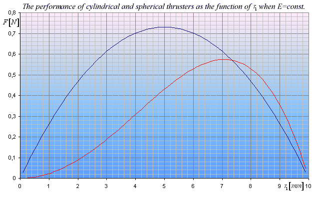
Diagram 4.
These formulas for Fc and Fs are very similar to those derived for the EP forces and the only difference is that instead of e we have a more complex constant coefficient. Therefore the same extreme values apply for these functions as demonstrated on the page discussing the EP forces, namely the highest thrust is predicted for the cylindrical thruster when r1 = 0.5r2, and in the case of the spherical thruster r1 = 0.707r2. These maximal values can be seen in diagram 4.
Diagram 5 shows the dependence of the thrust upon the relative permittivity of the first dielectric using the following parameters: Ex=1.5E7 V/m; rC1=0.5cm; rS1=0.707cm; r2=1cm; er2=4; l=2r2
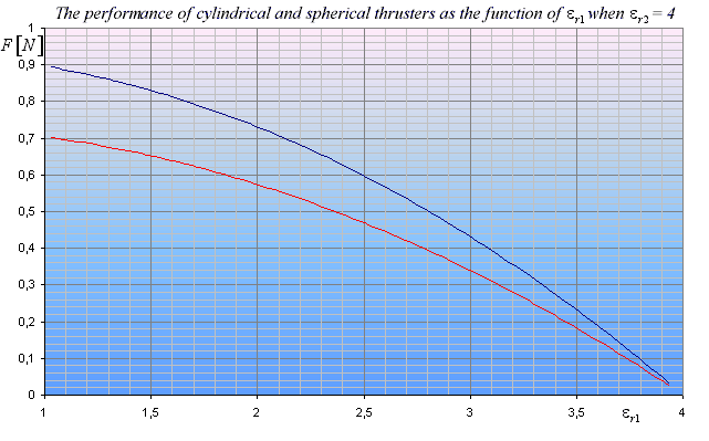
Diagram 5.
Conclusion
- We have derived the formulas for the real (complete) resultant thrust upon asymmetrical cylindrical and spherical thrusters through mathematical analysis, and the results are summarized in the following table:
|
As the function of U |
As the function of Ex |
|
Cylindrical thruster | |
|
|
|
|
Spherical thruster | |
|
|
|
-
These formulas predict significant thrust when applying high voltage and taking one dielectric to have high permittivity and the other low permittivity. This non-zero unidirectional reaction-less thrust (pointing towards the low permittivity dielectric) apparently violates Newtons 3rd law within the rough physical frame of reference, and it promises very efficient and clean propulsion and free energy generation for future applications.
The lowest limit of thrust
The above mathematical analysis was based on the assumption that the
local polarizing effective E-field intensity is 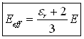 as
discussed in electromagnetic textbooks. The derivation of this formula is
based on the approximate assumption that the local E-field within the
examined empty spherical hole of infinitesimal size can be considered
homogeneous. Although this is a good approximation at infinitesimally
small dimensions when the polarizing E-field intensity is sought, a doubt
may still arise whether we can use this approximation when we want to
calculate the inhomogeneous E-field component that causes the resultant
dielectrophoretic force upon the elementary dipoles.
as
discussed in electromagnetic textbooks. The derivation of this formula is
based on the approximate assumption that the local E-field within the
examined empty spherical hole of infinitesimal size can be considered
homogeneous. Although this is a good approximation at infinitesimally
small dimensions when the polarizing E-field intensity is sought, a doubt
may still arise whether we can use this approximation when we want to
calculate the inhomogeneous E-field component that causes the resultant
dielectrophoretic force upon the elementary dipoles.
Therefore let us take the worst case, assuming the lowest possible inhomogeneous E-field intensity to create the dielectrophoretic forces in the dielectric that can not be less than the generally used real E-field intensity E. Using E instead of Eeff in the above analysis we can derive the formulas for the minimal resultant thrust using the same method and basic correlations. The formulas of the lowest thrust limits derived with this approach are summarized in the following tables:
|
Minimal CFE force of the
|
Minimal CFE force of
the |
|
|
|
|
Minimum |
As the function of U |
As the function of Ex |
|
Cylindrical |
|
|
|
Spherical |
|
|
Although these formulas predict somewhat lower thrust compared to the formulas of the first approach (derived using Eeff), they are still different than zero, and predict a significant thrust using properly chosen parameters.
|
disproved analysis based on the classical
model |
|