|
|
|
The E-field thruster project
The derived formulas in the theoretical part of the E-field thruster section predicted a reaction-less thrust originating purely from asymmetric electrostatic force distribution. This asymmetry can be achieved either by asymmetric electrode arrangement or by asymmetric dielectric distribution, or by using both asymmetries at the same time.
The given formulas represent only a first step approach, and their validity should be verified experimentally, and modified if necessary based on the measurement results. This is particularly valid for the edge-effect EE forces derived under the dielectrophoretic pumps, since the derivation of those formulas were based on the validity of energy conservation. According to the conclusions of that paper we have good reason to doubt in the validity of this law for the examined electrostatic systems, and consequently the derived formulas may also need correction. Therefore the theoretical research can not proceed further without first verifying the validity of the derived correlations for the partial forces present in the E-field thrusters.
Under the E-field thruster project we will publish some experimental results, and analyze their correlations with the theoretical predictions, and their implications.
The semi-cylindrical thruster molded into solid dielectric
The first experiment was started before deriving the formulas for the partial dielectrophoretic forces upon the dielectric. Its primary purpose was to detect any resultant thrust upon a semi-cylindrical thruster element fully merged into solid dielectric. A detected unidirectional thrust would unambiguously prove the presence of a reaction-less force, which is not developed by the ionization of the surrounding air.
Paraffin has been chosen as the dielectric due to its excellent
insulating properties: very high specific resistance of ![]() ,
relative dielectric constant of er
=2.1 2.2, and a high dielectric strength of 18 MV/m. Due to its
high dielectric strength and specific resistance even a thin layer of
paraffin is able to prevent any significant air ionization. The cross
sections of the thruster element are shown in the following two figures.
The rounded edges serve the purpose of minimizing the E-field intensity to
prevent the breakdown of the dielectric and air ionization, thus allowing
maximum E-field intensity between the electrodes. The proposed design
shows only an idealistic case, which can be modified if the practical
realization makes it necessary.
,
relative dielectric constant of er
=2.1 2.2, and a high dielectric strength of 18 MV/m. Due to its
high dielectric strength and specific resistance even a thin layer of
paraffin is able to prevent any significant air ionization. The cross
sections of the thruster element are shown in the following two figures.
The rounded edges serve the purpose of minimizing the E-field intensity to
prevent the breakdown of the dielectric and air ionization, thus allowing
maximum E-field intensity between the electrodes. The proposed design
shows only an idealistic case, which can be modified if the practical
realization makes it necessary.
The cross section of the thruster seen from the end.
The cross section of the thruster, side view.
The experiment has been conducted by Andreas Pramesberger. Even without any sophisticated instrumentation available He did excellent observations and we could derive valuable conclusions.
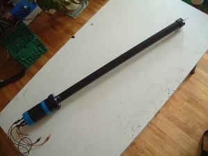
The characteristics of the prepared thruster are: r0=4mm, ri=2mm, the length of the thruster l=b=21cm, the applied voltage is about 26 kV. The thruster element was attached to one end of a rod. The rod was hanged up at its middle by a long thread while the other end of the rod was balanced with a counter weight. This setup represents a torsion pendulum that is very sensitive and can detect even small forces.
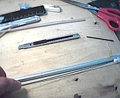
Making the rounded edges of the thruster element
When the layer of the dielectric cover at the thrusters bottom was thinner, a small negative thrust was detected (from the bigger electrode towards the smaller). By applying a thick layer of paraffin at the bottom (behind the edges) no thrust was detected. The negative resultant thrust can not be explained by any ion argument, and it is not developed by the movement of the air (just as the rocket does not moves in the same direction as the ejected burned fuel). If we would suspect that by making the paraffin cover at the edges thinner, a leakage current would ionize the air through the paraffin, then the thrust developed by such ionization would have to be directed towards the bigger electrode in positive direction. The observation indicates exactly the opposite, a negative thrust that must originate from the inner asymmetrical electrostatic forces (or some unknown electro-gravitational forces).
The resultant thrust can be increased by increasing the asymmetry of the partial electrostatic forces, applying different dielectrics between the electrodes and at the edges of the thruster. This can be a further object of experimentation. The observations and conclusions will be discussed in more detail later.
Cylindrical thruster project
The primary aim of the research is to obtain knowledge about the magnitude of all the partial forces present in the thruster, and their dependency upon the parameters of the system. As a starting point we can use the theoretically derived formulas for estimating the forces. The next step is to verify the validity of each formula separately with practical measurements and apply corrections where necessary. This can be accomplished when there is only one unknown force component in the total measured thrust that we intend to verify. Therefore we have to create such measurement setup and thruster in which this condition is fulfilled and the unwanted uncertain forces are eliminated.
If we assume that the basic formula for the electrostatic pressure on the surface of the conductors is valid (as it is stated by the official science of Electrostatics) then using a full cylinder with two different dielectrics in parallel between the electrodes we will have only one uncertain force component to be verified. Since the edges are eliminated there will be only two different types of force components. One is the electrostatic pressure EP component that we assume to be known, since it is calculated with the basic formula for the electrostatic pressure. The other component is the convergent-field effect CFE force that acts on the dielectric and attracts it towards the smaller electrode. The magnitude of this component was not known exactly with 100% security, since it was not clear what E-field acts on the elementary dipoles of the dielectric when the dielectrophoretic force is developed. Therefore two variants of the CFE formulas has been derived. One variant supposes a maximal local E-field intensity that is generally used in the analysis of dielectric polarizability of the elementary dipoles (or molecules). The other variant uses the macroscopic resultant E-field intensity present in the dielectric. Andis first experiment makes us suspect that the latest case might be true, but the first approach predicted too unrealistic values.
The cylindrical thruster with two different dielectrics
The partial cross section of the thrusters end
To clear this issue a cylindrical thruster element with two different parallel dielectrics should be constructed and the thrust measured for different voltages. This project requires measured numerical values of good accuracy, and requires some accurate instruments. Steven Dufresne has most of the required equipment and the missing HV probe has been constructed recently.
- The documented description of the construction can be found here.
- The related calculations of the protective spark gaps are posted here.
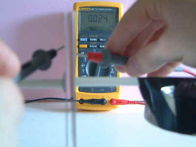
Steven has also done measurements of dielectric constants for some insulators that might be used in the thrusters.
- The documentation of the measurements can be found here.
- The site of Steven Dufresne about electrokinetic propulsion experiments is at: http://rimstar.org/sdprop
- The description of a professional method that served as the base for the measurements can be found here.
- A possible source of rough measurement errors during low capacitance
measurements has been demonstrated with a
test measurement here, to help avoiding wrong results.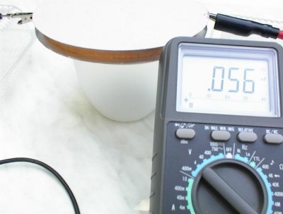
- A compact HV probe construction is described here.
- A sensitive HV torsion pendulum construction is presented here.
- The cylindrical thrusterproject's measurement results and a resulting discovery is described here.
Created by Zoltan Losonc (feprinciples@on.mailshell.com) on 6 September 2003. Last updated on 10 March 2004.
|
Project |
|