My HVG10 high voltage power supply puts out
from 24kV to 75kV positive with respect to ground whereas I needed
something that put out just a few thousand volts negative with
respect to ground, positive with respect to ground and ground too.
Luckily, my HVG10 contains a single circuit board immersed in mineral oil
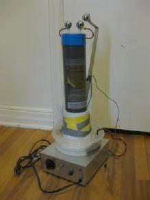
that is all that needed to be replaced in order to do this. Here's the resulting
power supply.
Positive/negative HV power supply...
 |
|
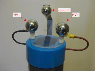
... and the possible connections.
 |
|
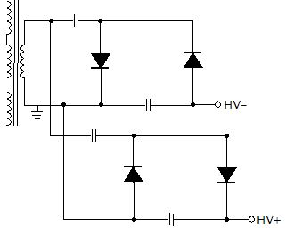
Most voltage multiplier schematics you see are for positive output. To get
both positive and negative output you need to add a second circuit in parallel
with the positive output one but with the diodes reversed.
The squigly lines on the left in the diagram above represent an AC source,
in this case a flyback transformer, which is part of the the input to the
circuit board and everything to the right is the circuit
board contents. A full schematic of an example of the input
(non-voltage multiplier) side, of things can be found on
this page about my 30kV power supply.
Construction details for the high voltage power supply
I ordered the high voltage diodes and capacitors both from
Information Unlimited,
the same place that I bought the HVG10 power supply from many years ago.
The diodes are their part number VG12 (12,000V, 10mA diodes, .625 x .13"
rectangular epoxy coated, unmarked, 100 nanosecond fast recovery devices for
use with high frequency switching circuits, avalanche diodes.)
The capacitors are their part number .001m/20KV (0.001microfarad, 20kV ceramic
disk capacitors.) Note that I didn't do any special calculations in selecting either of
these parts. I simply looked for inexpensive high voltage, high frequency diodes and
high voltage, non-electrolytic capacitors.
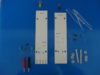
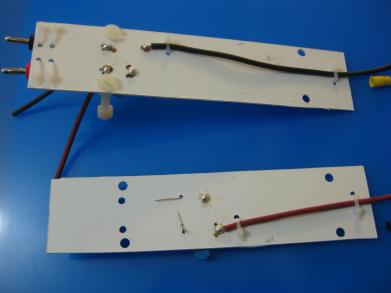
I just used sheets of 1/8" thick white plastic for the boards.
Any insulating material will do. These are the parts after drilling holes in the
plastic boards.
 |
|
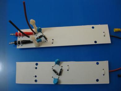
The completed voltage multiplier circuits. The negative
is the top board and the positive is the bottom. Note the two wire sticking
up from the negative board for making the parallel connection to the positive
board later.
 |
|
The backs of the boards. Notice that the soldering was done
with big rounded blobs of solder. Since this is high voltage, you want to avoid
any sharp metal edges. The two unsoldered, thin wires on the left half of the
positive (bottom) board are for the parallel connection, not made yet.
 |
|
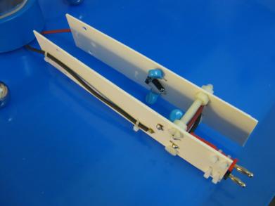
The two boards bound together with nylon nuts and bolts.
 |
|
Notice that the two wires for the parallel connection
have been pulled through the positive board and soldered to the positive
circuit.
 |
|
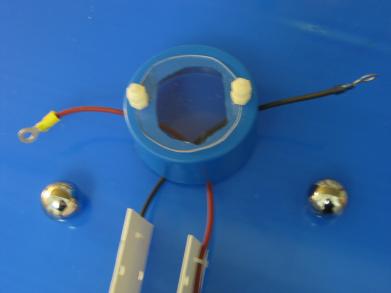
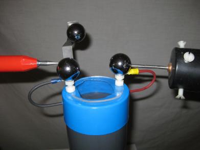
Two holes were drilled in the sides of the cap for the output wires. Two nylon
bolts were stuck up through the top of the cap. I didn't want to have the
HV- and HV+ steel
output balls sitting directly on top of the cap since any dust accumulated on the
cap would act as a conduction path between the two. So I raised them using
the nylon bolts. The reason for making the output wires so long outside
the cap was to make it easier to position the board inside the grey tube
before putting the cap on top of the tube. I also made a plexiglas window in the
top of the
cap so that I could check that the output wires inside the cap were not close
to each other.
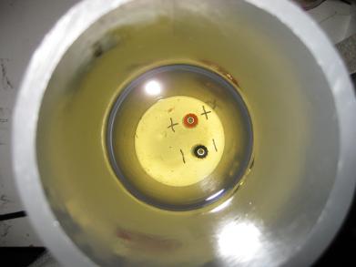
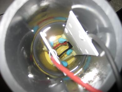
View looking down into the grey PVC tube at the banana connectors
at the bottom. The other side of these connectors goes to the flyback transformer
and to the ground connection.
 |
|
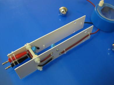
The circuit connected in place. Note that the part of the
circuit boards with the actual components on them are immersed in mineral oil to
prevent arcing between the components.
 |
|
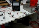
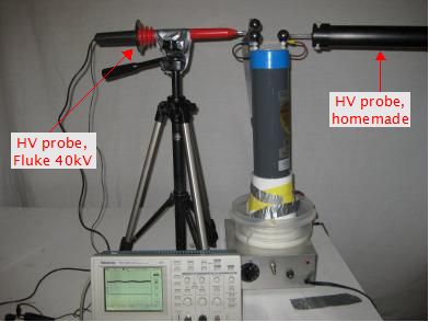
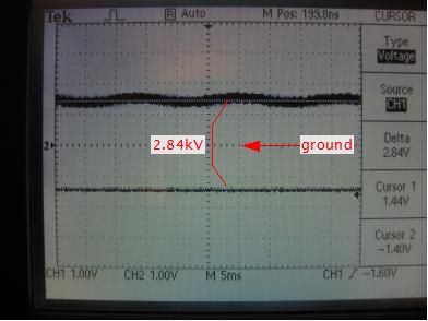
Testing the high voltage power supply
I used my store bought 40kV Fluke
HV probe connected to the oscilloscope's channel 1 to measure the negative
and my homemade > 40kV HV probe connected
to channel 2 to measure the positive, both relative to ground.
As you can see from the following photos, the combination worked.
The slight AC ripple on the upper line is noise
picked up by the homemade probe from the 60Hz household AC lines.
The result on the oscilloscope below is 2.84kV. This is the minimum
voltage, which is around what I need this for. I haven't looked for
the maximum. When the dial of the power supply is first turned up
and voltage first appears, the voltage is higher. I then turn it down
until around 2.8kV. If I go lower then the voltage quickly drops to zero.
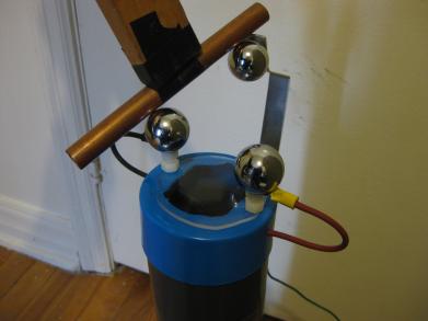
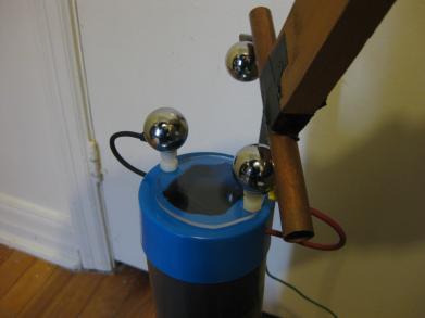
A bit about the ground connection and safety
The third steel ball is connected to ground. This isn't just for
convenience. When the power supply is turned off, the voltage slowly
goes to zero/ground. To make sure both positive and negative steel
balls have reached zero/ground potential and are safe to touch, I
have a long stick with a copper pipe taped to its end that I electrically
connect the negative and positive balls to the the ground ball with one
at a time as in the photos below. I keep the pipe in place for a few seconds
to make sure they've reached ground potential since it may take a little time
to drain capacitors. There is often a small arc when I do this. To be very safe,
I touch the ground ball first before touching a HV one. If I touched
a HV one first then the arc may find its way to ground through me instead of
through the air to the ground ball.