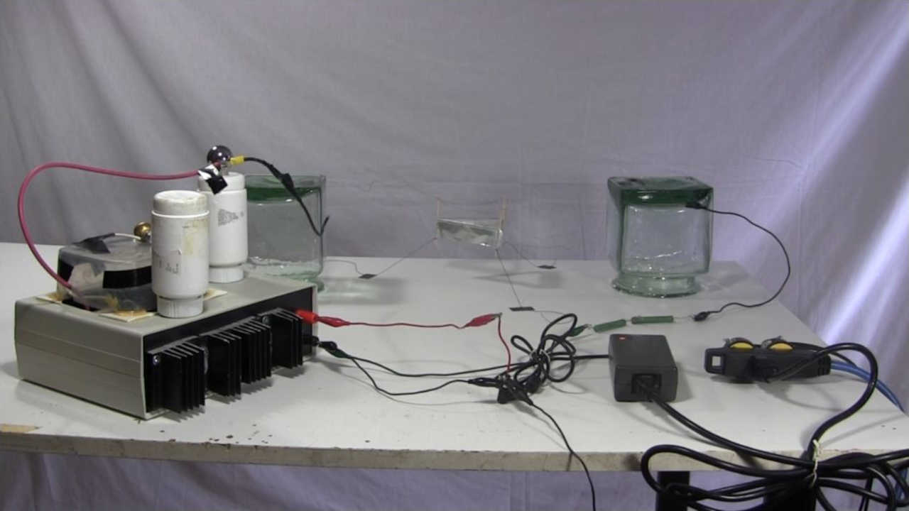
30kV DC Power Supply (homemade/DIY) using flyback and multiplier/tripler
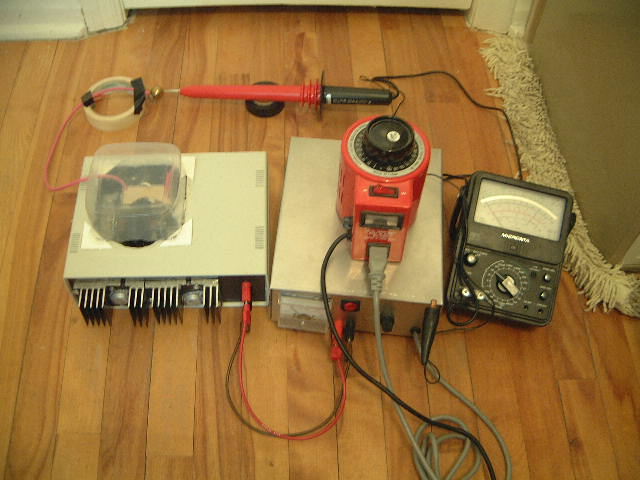
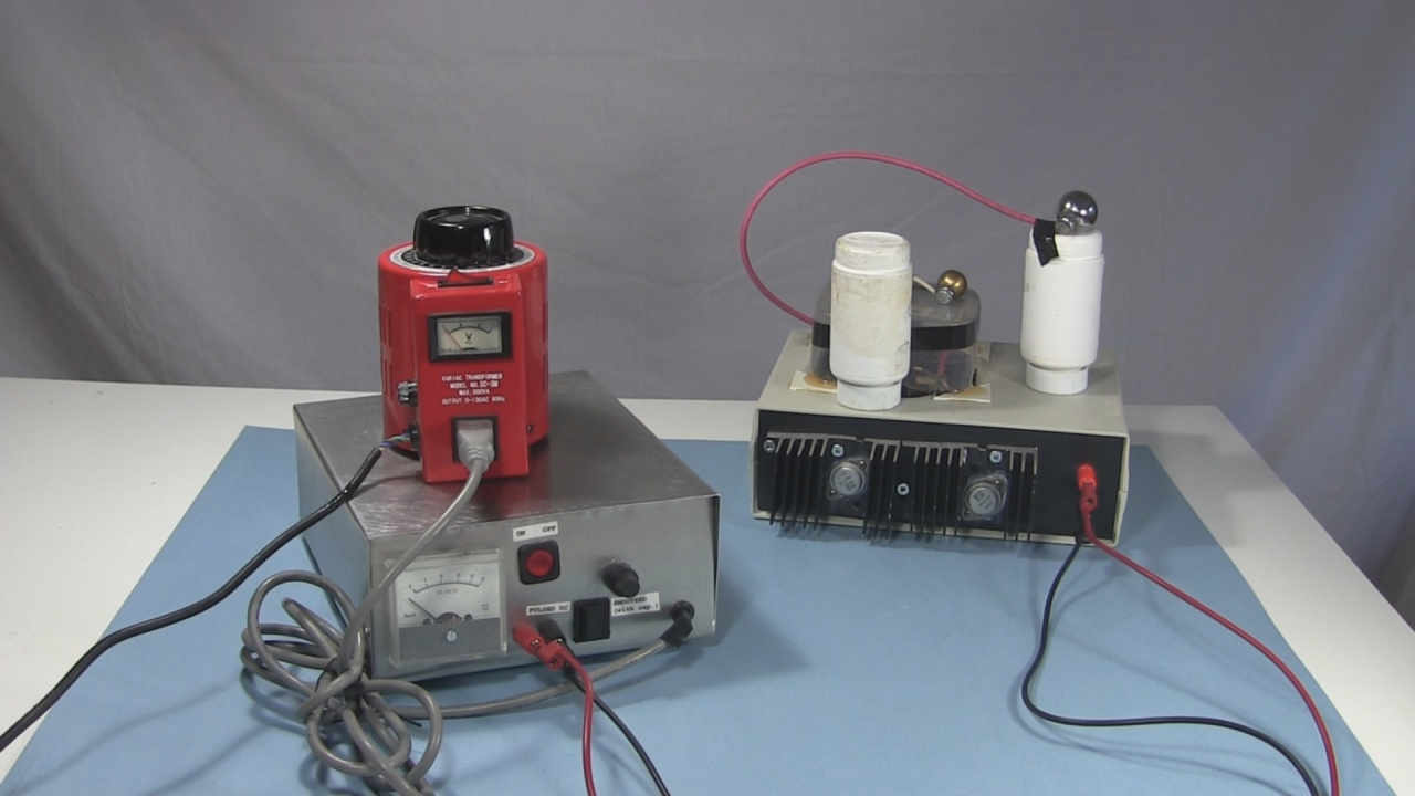
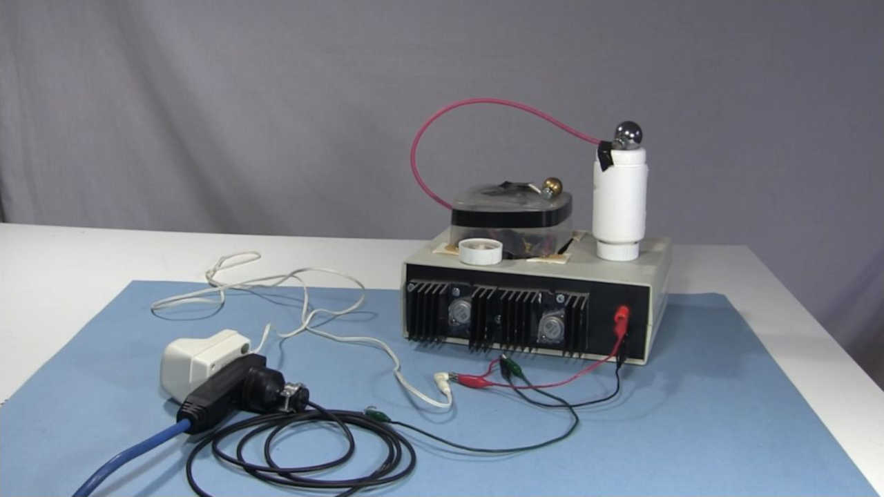
This is my DIY high voltage power supply. It puts out up to 30kV DC and expects to be fed by a source giving 0 - 24V DC. The input is through banana plug connectors. I usually feed it using my homemade 24V power supply but as shown below, I've also used a wall adapter and a laptop power supply. Also below is a video showing step-by-step how to make this high voltage power supply along with some demonstrations.


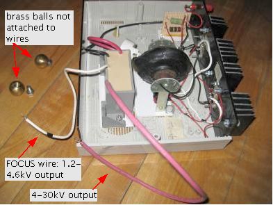
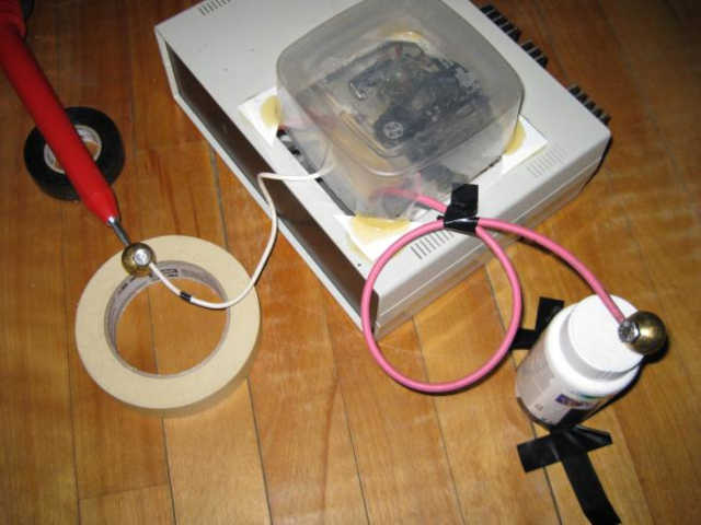
One modification I made is to make the FOCUS HV output from the multiplier (in this case also called a tripler since it triples the voltage) available. With the 30kV output wire I could get at low as 4kV but I wanted lower. So by making the FOCUS HV output wire available as an alternative I was able to get the range 1.2kV to 4.6kV.
It uses a flyback transformer to step the input voltage up to around 10kV AC and then feeds this into a multiplier which brings it up to around 30kV DC. I've looked at the output on my scope and it's fairly flat.
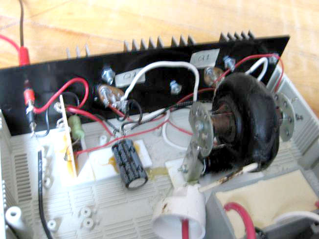
Transistor protection - capacitors and diodes
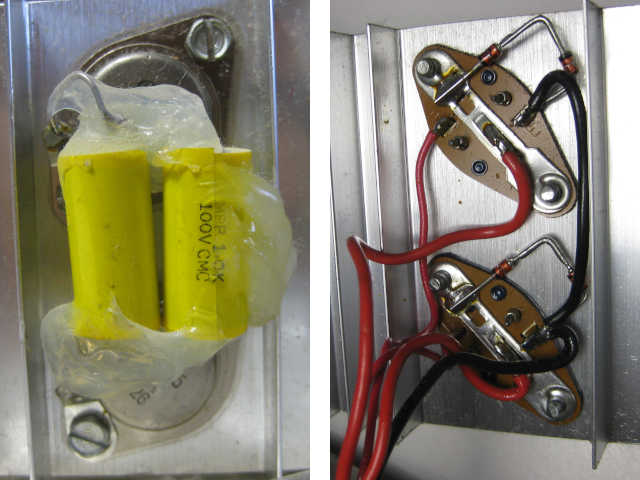
This is about the material in red in the above schematic. This is something I haven't tried myself but have seen done and heard about from others. I don't know much about it myself so I can only be vague. Repeating what I've been told, at least some of the purpose of it reduces the heating of the transistors and protects these bipolar junction transistors from negative going voltages on their collectors as they are vulnerable to that.
The parts in red in the schematic above are what are on my commercially made HVG10 power supply. The photos on the right are of these parts on the power supply.
From private email I've also been told that the recommended capacitor size is 200 to 400nF non-polarized, but 100nF works too. The diode is to be installed reverse bias and the recommended size is UF4007 or BYE500.
From a YouTube comment by Alex1M6 on my video about repairing a power supply I was told to "add a fast recovery diode across each transistor in the directions in the above schematic. For further protection put small film capacitors of around 10-47nF across each diode too and this will shift the transistors into quasi class E switching and can even reduce the heating of the transistors slightly. Larger value capacitors will reduce the output voltage slightly but will also reduce transistor stress, so experiment before finalising the value."
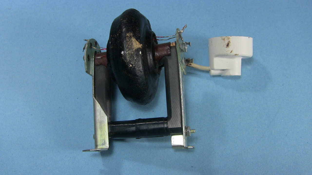
The flyback transformer
My flyback transformer was purchased from an online source which seems to be gone from the web. It's a very old one which doesn't have a built-in diode. Most flyback transformers these days have built-in diodes and it's difficult to find one which doesn't. I couldn't find it online anywhere but the part number information written on a datasheet which came with it is SD-FLY400, replacement for Motorola 24D67878A01.
I actually purchased two of them but burnt out the first one when I tested without the multiplier hooked up yet. I was lucky enough to get the flyback schematics along with the flybacks and on the schematics it gives the resistance across various parts of the flyback secondary. Using an ohm meter you can easily test whether the secondary of the flyback is any good. After I ruined my first flyback one of the segments of the secondary measured infinity (the wire was clearly broken). So it helps to have those schematics!
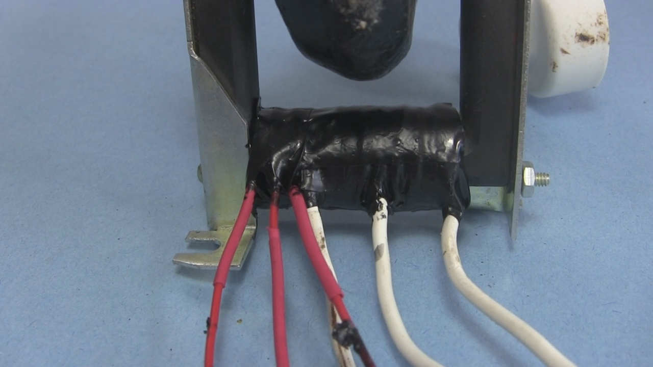
For the primary and feedback coils of the flyback I removed the wire that came with it and put on my own wires as detailed in the diagram above and as shown in the following photo. After wrapping the wires into place and taping them with black electrical tape, I then coated the result with a few layers of black liquid electrical tape for durability, gluing the whole thing.
The multiplier
The multiplier was ordered from a local electronics store and is NTE 521 from NTE Electronics, Inc. It has two inputs (hot and GND) and two outputs (focus and the 30kV output). NTE supplies a thick book of all their semiconductor parts (available at any store that specializes in NTE parts) and the schematic for the multiplier was in the book.
Many of the NTE multipliers can be used. A lot of them differ in the FOCUS output but the high voltage output is not affected by that.
Some have a 680 ohm resistor at the high voltage output and some don't. This won't make much difference for this power supply since if you expect the possibility of high power sparks (large spark gap building up a lot of power before sparking) then it's recommended that you put around 250 kilohms of at least 2 watt resistors at the output anyway.
Some are 5 step multipliers and some are 6 step. That means that the 6 step ones can start with a lower voltage input to get the same high voltage output as a 5 step one. But keep in mind they all have the same maximum continuous output rating under no load, 30kV at 2mA, except for NTE 559, which is 28kV at 2mA. The actual continuous output rating depends on what you give it as input and the maximum continuous output rating is the value you should not go over.
The following table has all the ones that I know of and that don't have extra POT, CTL or other inputs.
|
|
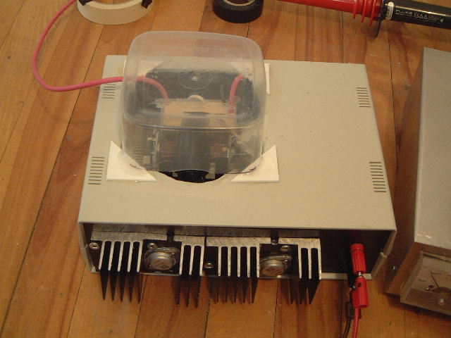
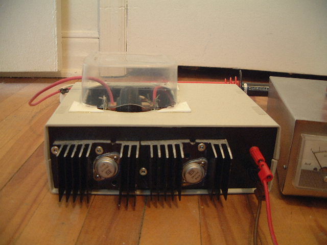
Construction and testing photos
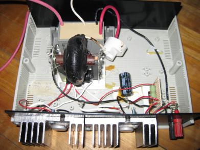
Click here for full details of where I got the heat sinks and how I mounted the transistors to the heat sinks.
IMPORTANT: It's recommended that if you might have high power sparks then you should put around 250 kilohms of resistance with at least a 2 watt rating at the output to protect the power supply from the high current of the spark. A high power spark usually comes from a wide spark gap. I damaged transistor Q1 this way by forgetting to put this resistance. I usually put it on the ground return side since it may involve uninsulated connections. My video below talks about how I found and replaced this damaged transistor. If you're curious about what I was doing when I damaged this transistor see this youtube video of mine, Star Trek Enterprise Model with Ion Propulsion added. The damage actually happened after the video was made and I was playing around some more.
WARNING: This power supply can produce harmful or lethal voltages and currents. Always discharge the power supply to ground after turning it off and before going near it. When making a corona, ion wind, sparking and/or arcing it produces ozone, which is harmful to your health, so use in a well ventilated area.
Feeding it 0 to 24 volts
As the above circuit diagram shows, this needs a 0 to 24 volt power source to feed it. I usually use my homemade 24V power supply but as the photos below show, I've also used a small wall adapter and a laptop power supply as well. The wall adapter has a switch for selecting the voltage, from 1.5V to 12V. The laptop power supply puts out only 20V and keeps it that way, even if I plug it into my Variac and try to control the voltage that way.
Video - How to Make 30kV High Voltage Power Supply
Here's my video showing step-by-step how to make this power supply. I also demonstrate it flying a lifter/ionocraft both using my homemade 24V power supply as the first stage and using a laptop power supply instead, which more people have access too.
Video - Fixing my High Voltage Power Supply
While experimenting with ion propulsion added to a Star Trek Enterprise model I broke this power supply for the first time. I could have avoided it if I'd followed my own advice and put around 250 kilohms of resistors (2 watts) in series with the output, but I didn't and ended up damaging one of the transistors.
The following video shows my steps in finding and fixing the problem.
