
This is an easy to make high voltage power supply uses the type of flyback transformer that has built in diodes, taken from a CRT (Cathode Ray Tube) type of TV. I'm calling it the Cube. With just a few additional parts, it can produce nice wavey arcs and even power a Jacob's ladder (traveling arc.)
The Cube
Flyback with built in diodes.
Wavey arc.
Jacob's ladder.
This is different than my 30kV high voltage power supply that used a flyback transformer without built in diodes and a Cockcroft-Walton voltage multiplier or tripler that contained the diodes (see photos below.) However, the multiplier does allow that one to get to 30kV. On the other hand, this commercially made multipler is hard to find, as it the flyback without built in diodes. The flyback with built in diodes used in this 20kV Cube power supply is easier to find.
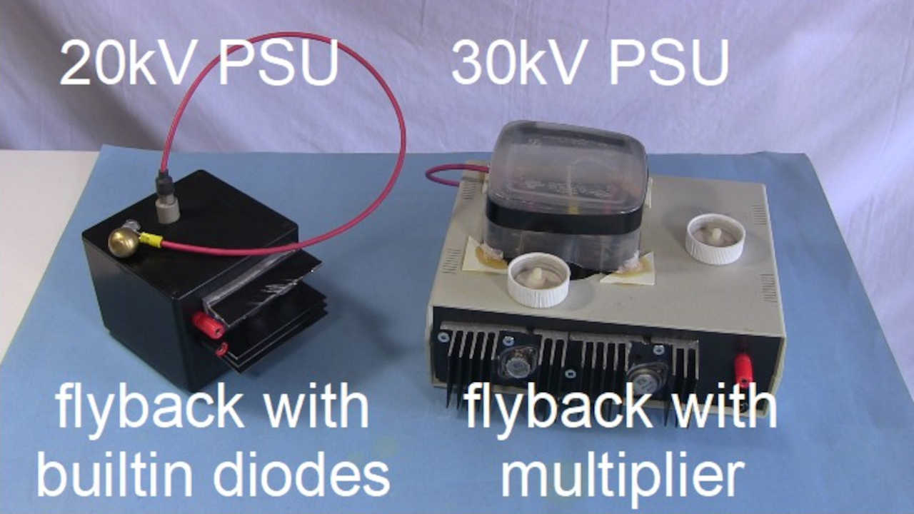
20kV and 30kV power supplies.
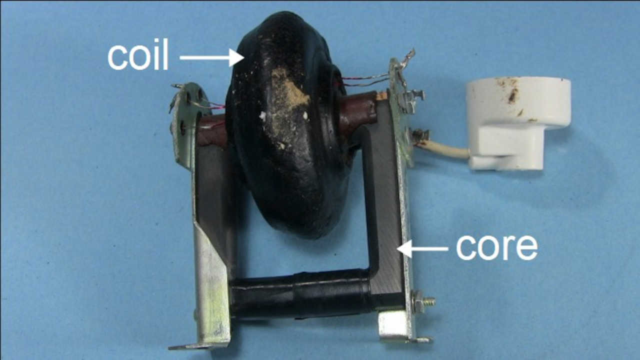
Flyback with no built in diodes.
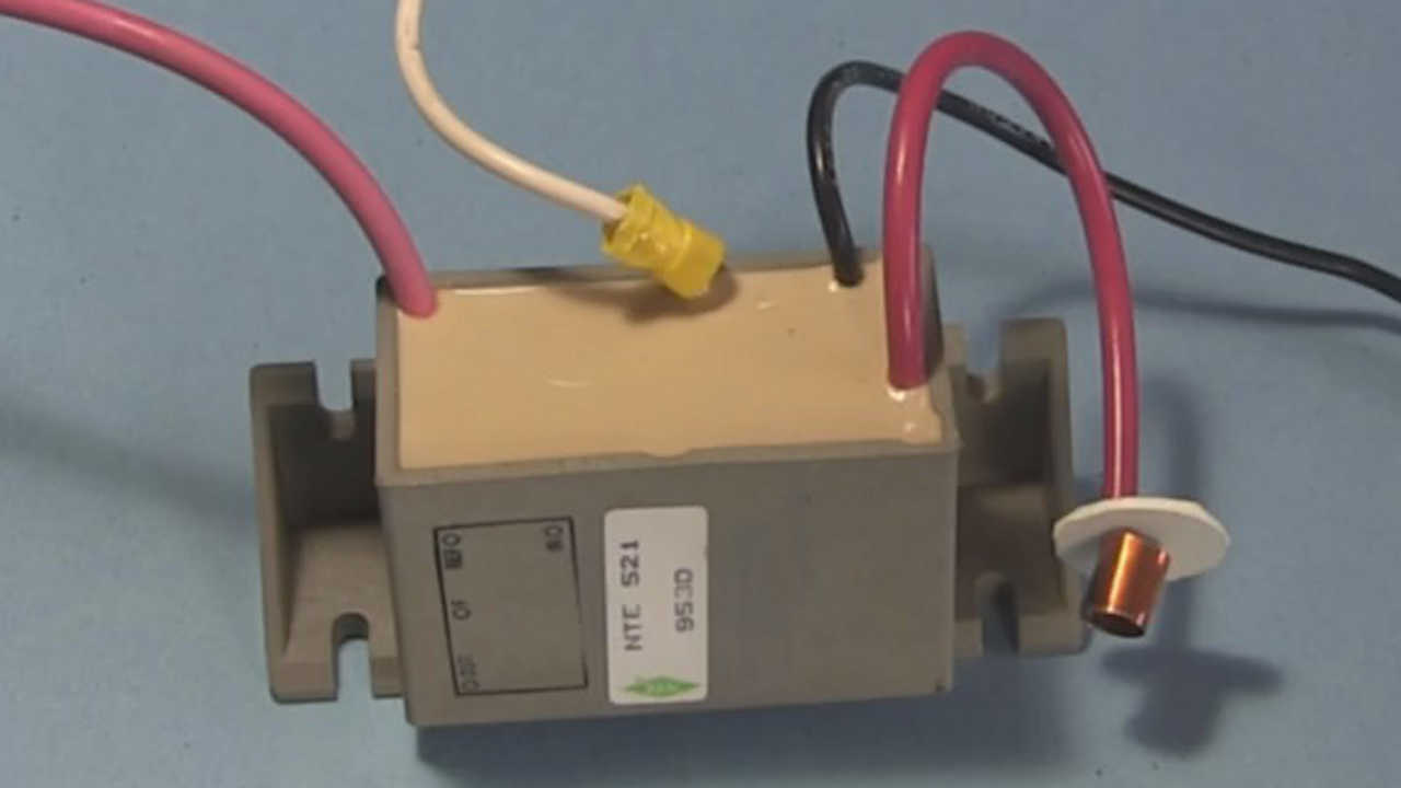
Voltage multiplier/tripler.
The following is a circuit diagram for this circuit.
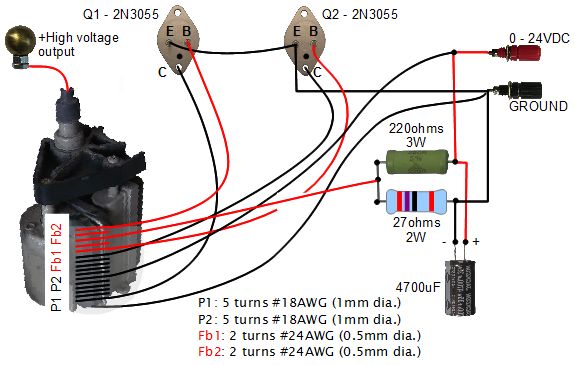
20kV DC high voltage flyback power supply circuit.
And here's the schematic. Note that I didn't add the parts that are in red. They're an enhancement talked about more in the Transistor protection section below.
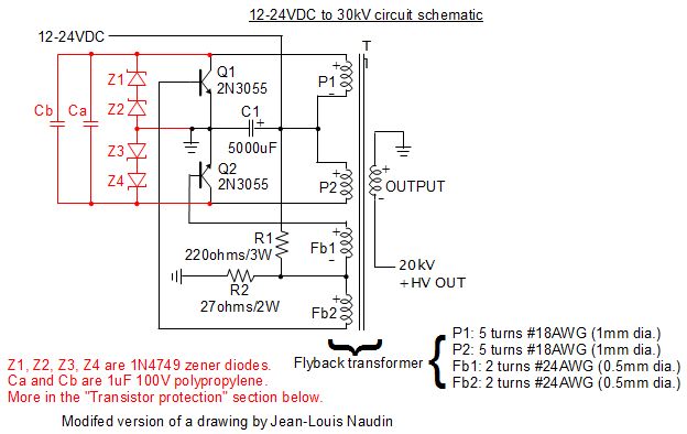
Flyback PSU with built in diodes schematic.
The flyback transformer didn't have any coils on the core so as you can see below, I added two, the primary coil (black) and the feedback coil (red). Both coils are center tapped, meaning that there's an extra wire coming from the center of each coil. The photo on the right below shows the wires before winding them on.
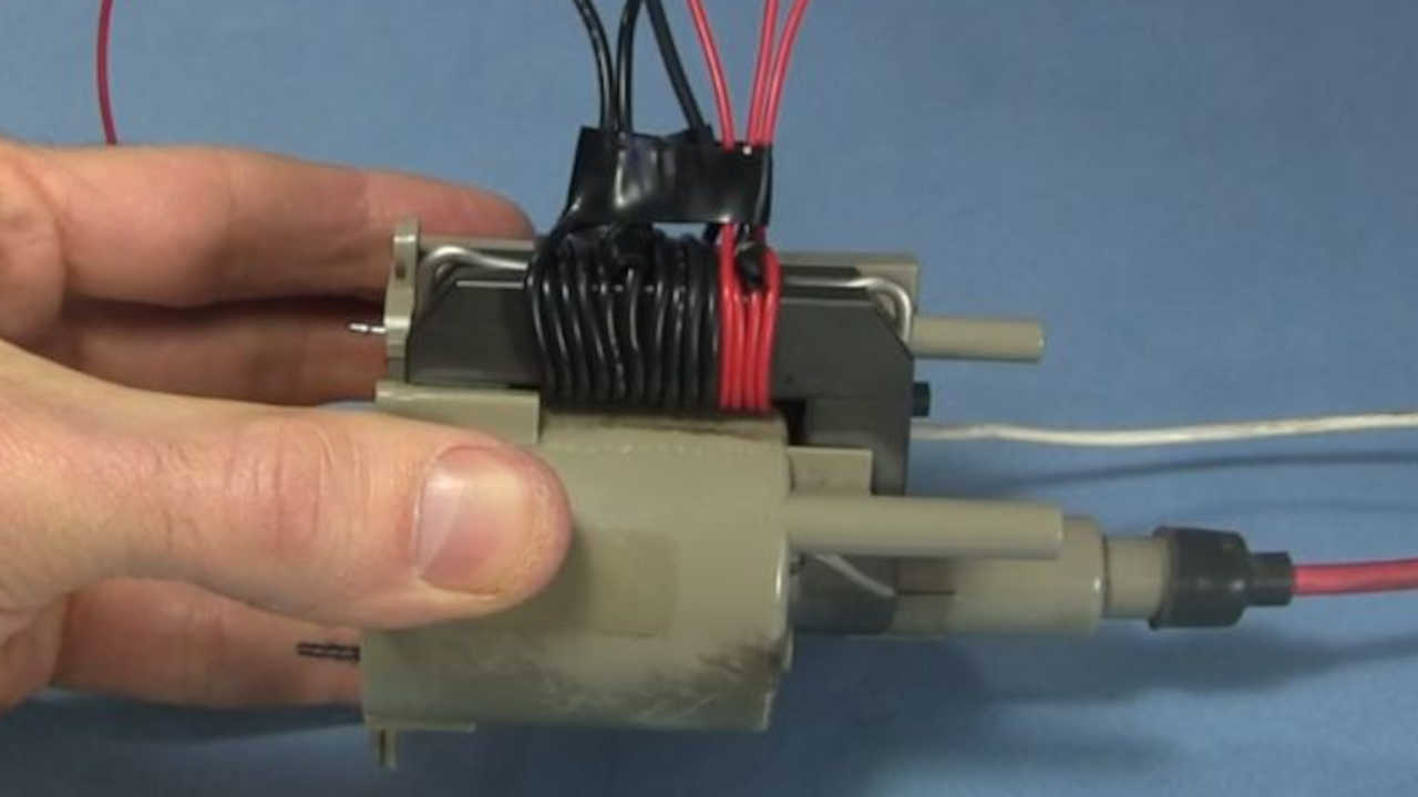
Flyback transformer coils.
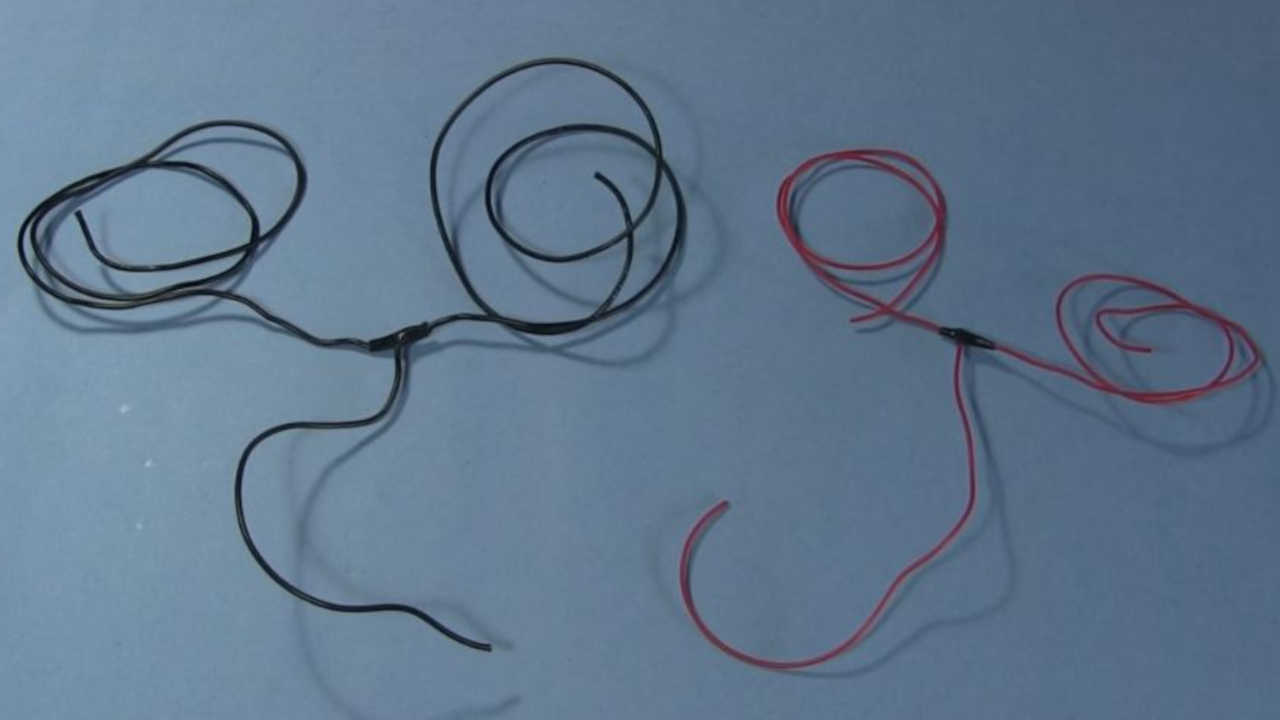
Wires before winding them.
Click here for full details of where I got the heat sinks and how I mounted the transistors to the heat sinks.
And is a photo of its interior.
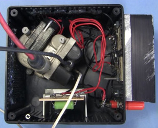
Looking down into the Cube.
WARNING: This power supply can produce harmful or lethal voltages and currents. Always discharge the power supply to ground after turning it off and before going near it. When making a corona, ion wind, sparking and/or arcing it produces ozone, which is harmful to your health, so use in a well ventilated area.
Transistor protection - capacitors and diodes
This is about the material in red in the above schematic. This is something I haven't tried myself but have seen done and heard about from others. I don't know much about it myself so I can only be vague. Repeating what I've been told, at least some of the purpose of it reduces the heating of the transistors and protects these bipolar junction transistors from negative going voltages on their collectors as they are vulnerable to that.
The parts in red in the schematic above are what are on my commercially made HVG10 power supply. The photos shown here are of the capacitors (yellow) and diodes (soldered to the transistor legs) on the power supply.
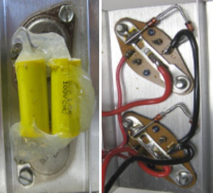
Capacitors and diodes for protecting transistors.
From private email I've also been told that the recommended capacitor size is 200 to 400nF non-polarized, but 100nF works too. The diode is to be installed reverse bias and the recommended size is UF4007 or BYE500.
From a YouTube comment by Alex1M6 on my video about repairing a power supply I was told to "add a fast recovery diode across each transistor in the directions in the above schematic. For further protection put small film capacitors of around 10-47nF across each diode too and this will shift the transistors into quasi class E switching and can even reduce the heating of the transistors slightly. Larger value capacitors will reduce the output voltage slightly but will also reduce transistor stress, so experiment before finalising the value."
The flyback transformer
As stated above, the flyback transformer is one with a built-in diode, as are most you'll find these days. It was randomly selected in that I found it in a TV someone had thrown away. Pretty much any flyback found on ebay.com will work.
From writing which was on the board near the flyback transformer, it said T505 and clearly it was a Sony flyback. From a no longer existing webpage that contained a list of Sony tranformers, it's Model KV32FS12, Version T505, Part Number 1-453-338-21. The KV32FS12 might be the Sony TV model number. The 1-453-338-21 was the part number, maybe just for that website. An alternative part no looks like it might be Sony part 1-453-338-11.
Using the high voltage power supply
Below is my setup for using this high voltage power supply (in this case it's powering a Jacob's ladder.) Notice from the circuit diagram above that the power supply takes 0 to 24 volts as input. I have my own 0 to 24 volt DC power supply that I use to give that input. The red thing sitting on top of it is a VARIAC, which is used to vary the voltage from 0 to 24 volts.
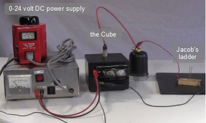
The setup powering the Jacob's ladder.
Below is a setup for measuring the output voltage using an oscilloscope and a FLUKE 80K-40 high voltage probe. I just touch the tip of the probe to the metal ball that's attached to the power supply's output.
As the oscilloscope output shows below, the voltage is 20 kilovolts. This was with 20 volts going into the high voltage power supply from the 0 to 24 volt power supply. I found that the input and output voltages scaled fairly linearly. 10 volts input gave 10 kilovolts output, and so on; whatever the input voltage was, the output would be 1000 times that. I also found that at 20 kilovolts and higher, the transistors would start getting hot much faster.
To reduce the transistor heating problem it was suggested that I could add some capacitors and diodes across the transistors. You can find more about that under the heading "Transistor protection" on my 30kV power supply page since it uses practically the same circuit.
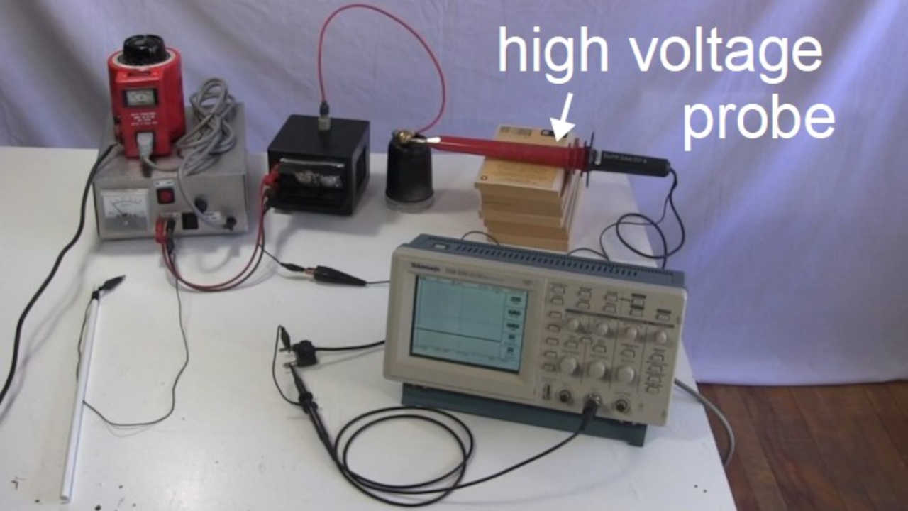
The voltage measuring setup.

20 kilovolts.
I also did some current measurements, but without measuring the voltage at the same time. These were done both while sparking and while drawing a constant, wavey arc. To make the measurement an analog meter was used (see below.) A wire with an alligator clip was taped to a plastic stick. The tip of the alligator clip was placed near the metal ball output of the power supply while the other end of the wire went through the meter to ground.
As you can see, the current can be over 250 milliamps, which is lethal if it goes through your heart.
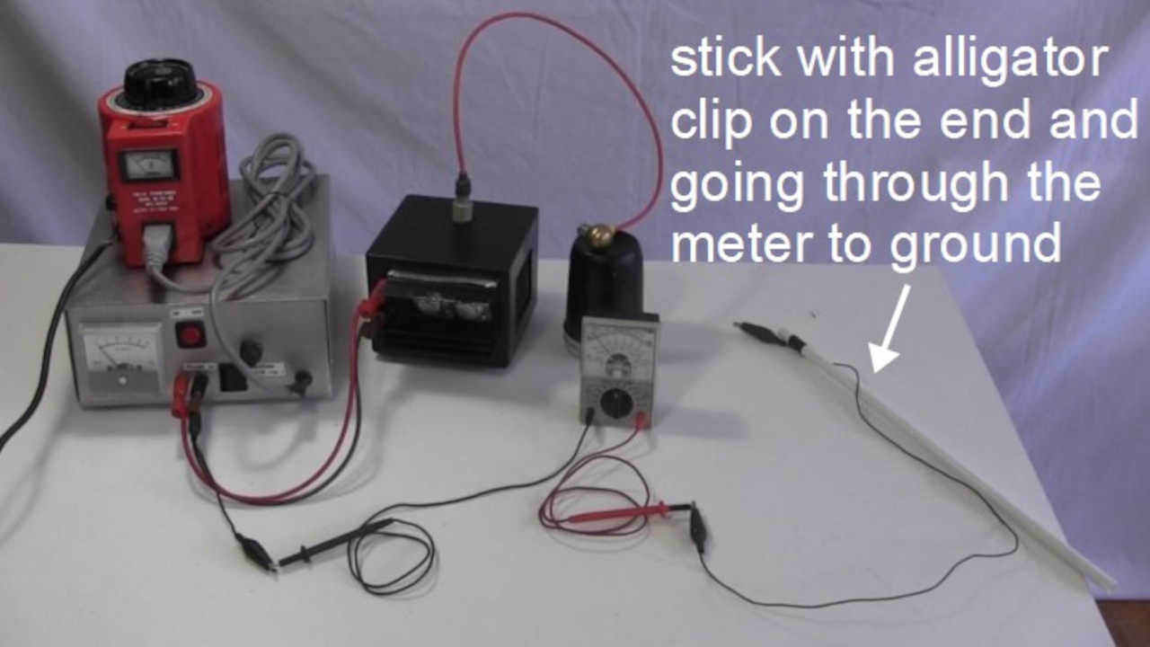
The current measuring setup.
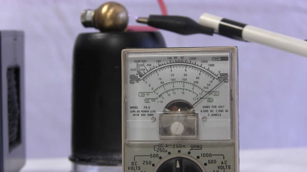
The needle is off the 250 milliamp scale.
Video - The Cube - How to Make High Voltage Power Supply w Flyback/Builtin Diodes
Here's my step-by-step instructional video for making this power supply, along with some voltage and current measurements, and demonstrations.
