Lifter/ionocraft experiments
The objective is to experiment with the lifter/ionocraft technology modeled on the work of Transdimensional Technologies (whose former website was http://www.tdimension.com though it no longer exists.) Lifters are also called ionocraft, but the original name for the three sided, aluminum foil craft was lifter so I'll call it that most of the time.
The lifter is a typically triangular shaped, lightweight device capable of lifting its own weight. However, it cannot also lift the weight of its high voltage power supply that powers it. The basic components are two conductive electrodes, one having a sharp edge (usually a very thin, bare copper wire on the order of 30 to 50 AWG/gauge), and the other having a smooth edge (usually aluminium foil.) The rigid structure is typically make of very thin balsa wood sticks (around 2mm or 1/16" thick) or straws. Glues such as krazy glue (filler type) or cyanoacrylate are very effective for holding it together while not requiring much and also being lightweight.
Voltages needed to power it are typically 20kV and higher. Most experimenters use a modified computer monitor as the high voltage power supply as most are capable of supplying around 28kV. Note that the power supply must also be able to supply a useful amount of electrical current since the top wire will be either leaking or collecting electrons as it ionizes the surrounding air. This requirement means your average Van de Graaff generator or Wimshurst machine may not be able to make it fly since they supply only low microamps of current.
Devices, Experiments and Calculations
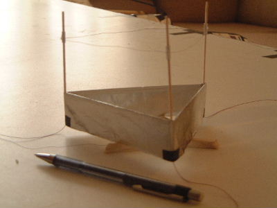
- Lifter 1a - Quickly thrown together single triangle, 75mm edge length lifter
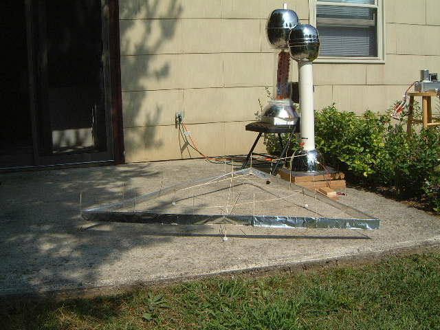
- Lifter 1b - Single triangle, 130mm edge length lifter
- Wind tests
- Thrust tests with a wind-shielded triple beam scale
- Theories with theoretical calculations for how lifters work
Tips for getting your lifter to fly
- Make your lifter as light as possible. A three-sided triangle lifter typically needs to be on the order of 2 grams to be light enough to fly. This is a rough benchmark as there are many parameters, but is good for most newbies. Both heavy and light aluminium foil is available in the grocery stores. Use the light one. I use balsa wood sticks which are about 1.5mm (1/16") square when looked at from the end. These are available from hobby shops. Another source of weight is the glue that you use. Hot glue tends to be used in big globs and adds weight. Cyanoacrylate glue, Krazy Glue or Superglue work well.
- The thinner the wire the better the result. Typically 30 AWG (American Wire Gauge) or thinner is used. The higher the number the thinner the wire. The wire must be bare, no insulation. "Magnet wire" has a thin coat of insulating material which can be stripped off with sandpaper, or the edge of a sharp knife (be careful not to break the wire) or by dipping in paint thinner. Magnet wire is available in rolls but can also be found as coils in various electronic devices. Thin bare wire is also available in roles. You can also get wire by stripping a plastic insulated wire that is made up of many strands. Don't worry about roughing the surface of the wire with sandpaper. A rougher surface is better since it will ionize the surrounding air more.
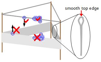
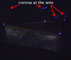
- The top edge of the foil must be rounded, as in the drawing above. If it's not then you will ionize the air at that top edge. The ions will be attracted to the wire. Meanwhile, ions from the wire will be moving toward the foil. The end result will be a conductive purple/blue corona between the foil and wire. This corona is like electrically connecting the foil to the wire. Your voltage will be very low and you'll get no lift. You want ionization at the wire, not the top of the foil. Again, see the picture above.
- Arcing, or sparks, are a bad thing and are an indication that you should increase the distance between the wire and the foil. Arcs also blow tiny holes in the top of the foil. This causes the top of the foil to be more leaky, as if it had a sharp edge.
The number one tip for getting a lifter to work is to run it in complete darkness, while taking all safety precautions such as turning on the lights and discharging the high voltage before making any adjustments. In complete darkness you can see the corona. If only one side is rising, you'll see corona only on that side. Adjust the wires so that the other sides are getting corona at the wires too. In the photo on the left below you can see corona along one side and at the corners for the other sides.
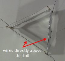
As shown below, the wires should be as directly above the foil as possible.
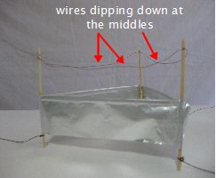
If you're really having problems, try making the wire dip down along the middle of each side so that the corona is mostly along the middle. If you don't then most of the corona will be at the corners, which also works.
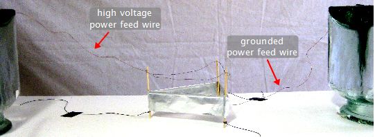
As shown in the photo below, the wire feeding power to the foil should be the grounded wire. That's because the table is also grounded and so the wire and table won't interact with each other electrically too much.
Depending on how you shape these wires, they can also produce downward pressure on the lifter, preventing it from flying. This is another thing you can play around with to get it to fly.
Video of step-by-step instructions for making a lifter
The following is a video of how I make my lifters.
How a lifter works
I have a more detailed page on how ion propulsion works, which is what makes this lifter fly but here's a brief summary. The key is having two electrically charged objects of opposite polarity, one that's sharp and one that's smooth. In the lifter the sharp one is the wire and the smooth one is the smooth top edge of the foil (it may work with the top edge of the foil cut sharp too, but it doesn't work as well and the charge is spread a bit along its surface too so it's not considered as sharp as the wire.)
The sharp wire ionizes the surrounding air and the smoother foil doesn't, or not as much. The ionized air moves toward the smoother foil and bumps into neutral molecules on the way, transfering momentum to the neutral molecules. It's that transfer that causes the lifter to move back in the direction the ions came from.
The neutral molecules and some ionized air is what makes up the downward flowing wind that is detectable in smoke tests, the ion wind.
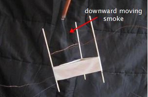
There is some dispute about this. Everything is claimed from antigravity, ether reaction forces to more conventional ion wind and ion cloud theories. It's claimed that the ion wind theory has been disproven with experimentally verified mathematics a few times as giving insufficient thrust. However, as you can see from the smoke test shown on the right (and more on the lifter wind tests page), there is clearly a great deal of downward airflow, mostly through the middle. The possible error in this disproof is that the experimental verification was made by measuring only the downward wind below the lifter. That doesn't take into account the downward moving air molecules that run out of momentum on the way down as more and more collisions occur. Ultimately a lot of the molecules' downward momentum is lost to heat i.e. it results in random motion.
The theory that has the most experimentally verified mathematical support is the ion cloud theory, which accounts for those molecules which did not make it all the way down. See Leon Tribe's calculations though others have also provided mathematical support for this theory.
Video - How Ion Propulsion, Lifters and Ionocrafts Work
Here's a video I made showing in detail how this ion propulsion for lifters or ionocraft work.
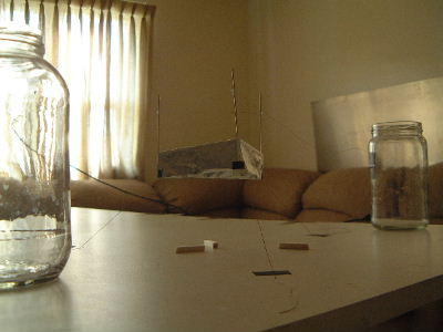
Video showing measuring voltage, current and airflow (using a smoke test)
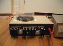
The following shows how I measure the lifter voltage and current, including the setup, as well as observing airflow by doing a smoke test with an incense stick. To measure the high voltage I use my Fluke 80K-40. The power supply used is my homemade 30kV high voltage power supply.
Where to get a high voltage power supply for your lifter/ionocraft
WARNING: The high voltage power supply needed for lifters or ionocrafts also puts out a dangerous amount of electrical current. It needs to do this in order to keep creating the ions for flying. This amount of current and voltage can cause injury or kill. Do not do this unless you know what you are doing and take proper safety precautions.
There are three places to get high voltage power supplies:
Also, click here for tips and tricks on high voltage wiring which I've come up with over the years.
