Vacuum Cleaner Motor and Supporting Structure

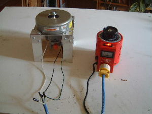
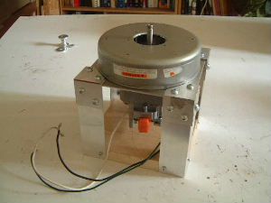
I needed a vacuum cleaner motor for use in propulsion experiments involving high speeds (RPMs). Vacuum cleaner motors can typically do 10,000 RPM with plenty of torque. So I purchased one brand new ($150 CDN). It is an AMETEK Lamb Electric Division part number 315923. It is a 120 volt motor, 50/60Hz AC or it can be 120 volt DC (since it can do either AC or DC it is refered to as a universal motor). At maximum speed (and hense maximum voltage) the motor pulls 11.X amps (I don't recall the value of X). I could have gone with a smaller, cheaper one but I wanted the longer shaft that this one has. The really nice thing is that the shaft is threaded at the end, making it easy to attach things to it. It is variable speed if controlled by a variac or speed control.

Side view. The fan layers have already been removed (talked about below).
Side view of bare vacuum cleaner motor.
Setup for a non-conventional propulsion test using the vacuum cleaner motor.
Setup for a non-conventional propulsion test using the vacuum 
      cleaner motor.

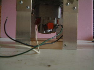
This vacumm cleaner motors sucks air in from the shaft area and down through the body of the motor. That's how it cools itself. For propulsion experiments this is an issue as this airflow can distort results. This can be solved by putting the motor and device under test completely in an airtight box. That box then becomes the thing you put on a scale or balance. Since no flowing air can get out, this airflow will not be a factor.

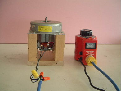
Vacuum cleaner motors have a lot of torque so you'll want to slowly bring it up to speed. This can be done using a variac or speed control.

Working with high rotation speeds is dangerous! If parts come off of your device they will fly at deadly speeds. Always be completely behind a protective barrier or in another room altogether (maybe with a camera and TV monitor setup) when the motor is spinning something at high speed.

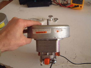
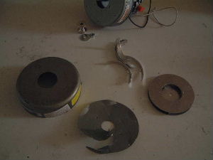
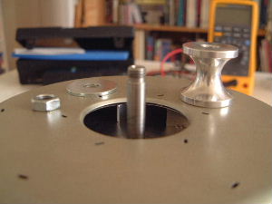
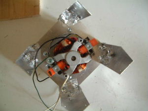
To expose more of the shaft I had to remove some of the fan layers on top (pictures below). This motor had three fan layers for sucking in air. The layer closest to the end of the shaft was a rotating. The next layer was a nonrotating one. And the last layer was a rotating one. I removed the first and second fan layers so that I could expose more of the shaft for my use. As of this writing I still have the third, rotating fan layer so that it can cool the motor. I may or may not take it off later and either always run the motor for short enough periods of time so that it does not heat up or have a separate cooling fan.

These are the pieces I removed. The round thing on the right was the top rotating fan layer. The rounded strips to the left of it were the blads for the second nonrotating fan later. The first part I removed was the round cap on the left. This was done by gently pounding a chisel in the area where this cap met the cap the is still attached. It is held on just by a tight fit.
Various parts removed from the fan part of the vacuum cleaner motor.
The shaft after the fan layers have been removed. There is still one fan rotating layer inside (you can just see the ends of two of two blades on either side of the shaft). The hourglass shaped part slides down onto the shaft to hold that fan layer in place. The washer is put on next and then the bolt.
The vacuum cleaner motor shaft.

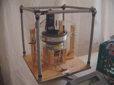
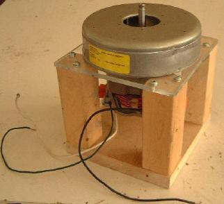
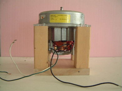
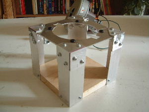
I needed a strong but lightweight supporting structure for my vacuum cleaner motor so I built one. Pictures follow.

The completed lightweight supporting structure I built. The base is a hardwood (oak or maple, I don't know which). The legs are cut from 2x4s which were then trimmed to be narrower. The plate that the motor is sitting on/attached to is made of 1/4" thick Lucite.
The lightweight wooden support structure for the vacuum cleaner motor.
This is just showing the cleanance I left under the motor for airflow and who knows what else I'll do in the future.
Photo of the clearance between the vacuum cleaner motor and the 
      bottom of the lightweight wooden base.
The motor turned on. The blue cable that the loose wires are attached to is the same one plugged into my variac on the right. The black cord coming out of the variac is going to the wall socket.
The vacuum cleaner motor connected to the VARIAC for speed control.

The following is the first supporting structure I made. It is all metal. The problem with this was that some experiments involved high voltages or had moving magnetic fields that could induce eddy currents so I made the above one with less metal.

The completed lightweight supporting structure I built. All the metal parts are aluminum. The base is a hardwood (oak or maple, I don't know which). The legs are cut from 3' L shaped aluminum which is available from most big hardware stores. Each leg of the L is 1.5" wide. On the top you can see four small black things. Through them are the holes for screwing the motor in place. Each black thing is half a rubber grommet. I use them there to possibly soak up some of the vibration, if any.
The all aluminium support for the vacuum cleaner motor.
The motor in the supporting structure but upside down and with the wooden base removed. I took this so you could see that all the washers and bolts on the inside that might come loose (look at the four corners) are covered in aluminum tape so that if they did come loose they wouldn't go flying into the motor. Usually a glue would be used for this but I didn't want it to be too permanent.
The underside of the all aluminium support for the vacuum cleaner motor.
The motor in the completed supporting structure.
The completed all aluminium support with vacuum cleaner motor in place.
This is just showing the cleanance I left under the motor for airflow and who knows what else I'll do in the future.
Photo showing the clearance between the bottom of the vacuum
      cleaner motor and the base.
The motor turned on. The blue cable that the loose wires are attached to is the same one plugged into my variac on the right. The black cord coming out of the variac is going to the wall socket.
The vacuum cleaner motor in the all aluminium support and
      connected to the VARIAC for speed control.
rimstar.org
Contact:
Liked this? Share it with: