
This is an attempt to replicate the experiment described in European patent EP 0486243, Machine for acceleration in a gravitational field by Haruo Tamashita and Takayuki Toyama.
Patent Experiment Description
|
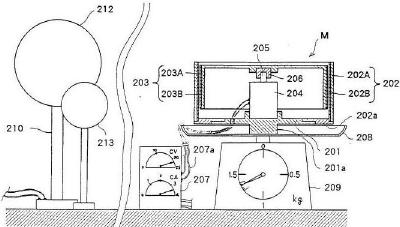
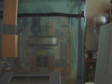
Figure 3 above is the first experimental setup described in the patent. 203 is the rotating cylinder consisting of the conductor layer 203A and an outer dielectric layer 203B. 202 is the stationary cylinder consisting of the outer conductor layer 202A and an inner dielectric layer 202B. There is a 2 mm air gap between the dielectric layers, each dielectric layer being 5mm thick. 210 is a Van de Graaff generator with a spherical negative electrode 212. 213 is used for testing the reversed polarity.
The patent has more details about the experiment, including the steps taken to do the experiment rigorously, but basically when the stationary conductor is negative with respect to the rotating conductor the unit loses weight. When the polarity is reversed the unit gains weight. The direction of rotation has no effect on weight change.
My Experiment Attempt
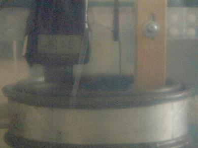
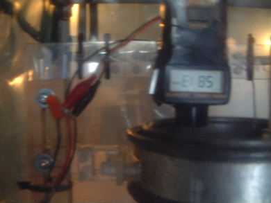
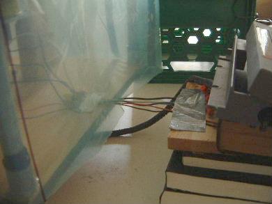
In my setup I will be orienting the rotating electrode upside down with respect to how it is in the patent. The open end will be up. This is because of the large size of my motor. The pictures below show this.
|
|
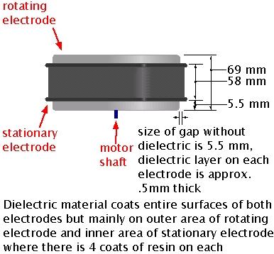
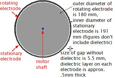
The rotating electrode will obviously be attached to the shaft of the motor. The stationary electrode will be attached to the motor frame likely by both being attached to the same base. This means that other than for rotation, the two electrodes are will not move with respect to each other.
Note that there are no sharp edges on the electrodes thereby keeping the electric field strongest where the electrodes are facing each other.
Construction
My efforts at construction have consisted of the following so far.
- Sept 21-24, 2004 - Purchase of a motor and construction of a supporting structure
- Sept 27-30, 2004 - Mounting of the rotating conductor and some tests
- Oct 15-29, 2004 - Making the electrodes
- Nov 22, 2004 - Added mounting pieces
Testing for weight change using digital scale - Dec 8, 2004
|
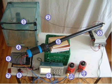
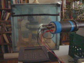
In the picture above: (1) cylinders and phototachometer mounted in test stand under the green plastic cover (digital scale is sitting on the table underneath all this), (2) high voltage wire going through plastic to stationary cylinder, (3) high voltage power supply, (4) power and control wires (motor power, ground, phototachometer power) (5) high voltage probe, (6) control unit for digital scale (the digital scale is under the test stand), (7) playing card, (8) batteries and on/off switch for phototachometer, (9) oscilloscope, (10) variac for controlling vacuum cleaner motor speed, and (11) variac for power supply.
|
|
|
If you don't have QuickTime you can download it here.
More details and pictures of the test setup can be found here.
The test procedure was:
- The scale was set to 0.0.
- The playing card was gently placed on top of the green plastic cover on the test stand. The scale reading changed over about 1 second from 0.1 grams to 1.7 grams and stayed at 1.7 grams, the weight of the card. The card was then removed and the scale went back to 0.0.
- The high voltage power supply was turned on and turned up to around 14kV. Any higher and arcing would occur between the cylinders. The scale continued to show 0.0. The power supply was turned off and discharged.
- The vacuum cleaner motor was turned on and the speed was slowly turned up to around 3300 RPM. Throughout this the scale showed 0.0.
- The high voltage power supply was turned on, already set to around 14kV. The scale remained showing 0.0.
- The playing card was again placed on top of the green plastic cover on the test stand. The scale reading changed to 1.7 grams. The card was removed and the scale went back to 0.0.
- The high voltage power supply was turned off and discharged. The scale still showed 0.0.
- The speed of the vacuum cleaner motor was gradually turned down to 0 RPM during which the scale continued to show 0.0.
Conclusion is that there was no weight change by the device.
Possible reasons why there was no weight change whereas there was in the Haruo Tamashita and Takayuki Toyama patent are:
- The spacing between the conductive material of the cylinders was different. Mine was .5mm dielectric - 4.5mm air - .5mm dielectric. The one in the patent was 5mm dielectric - 2mm air - 5mm dielectric.
- The relative heights of the cylinders was different.
- The voltages were likely different. No voltage information is given in the patent and was probably not measured.
Testing for effect on object beside cylinders - Dec 10, 2004
At Steven J. Smith's suggestion I did a test to see if there would be any effect on a small object hanging beside the cylinders. To do this I hung a small marble (weight 5.4 grams) from the ceiling using a very thin and light cotton/polyester thread (length 1420 mm). Because there would be air currents within the test stand's plastic cover I hung it so that it was close to the outside of the cover. The distance from the center of the marble to the nearest outer edge of the stationary cylinder was approximately 160 mm.
|
|
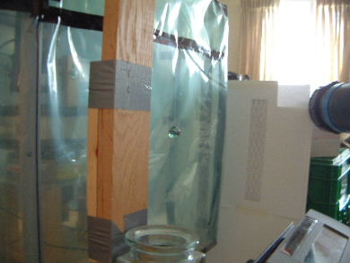
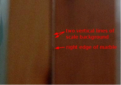
In the middle of the picture on the left you can see the marble. The white sheet to the right of the marble is a piece of paper with vertical black lines on it to act as a scale. The paper is taped to a sheet of plastic for rigidity. To the left of the marble, the pieces of wood duct taped together make up a "sighting notch". The two pieces of wood are actually spaced apart 0.023 inches using cardboard spacers. The idea is to look through the space between the boards to the marble, lining it up with one of the vertical lines on the white piece of paper behind it as shown in the picture on the right. Any movement is easily visible and due to the long narrow space that you are looking through, the movement would not be due to any movement of your head as moving your head would cause you to no longer be able to see through the slot at all.
The test instruments had to be moved around a bit from the weight testing done on Dec 8, 2004 as the following picture shows.
|
|
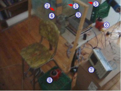
In the picture on the left, the following are worth pointing out: (1) the marble, (2) the sighting notch through the wood pieces, (3) the vertical line scale, (4) a large piece of plexiglass in a wooden frame for sitting behind when looking through the sighting (in case the cylinders fly apart at high speed, normally with the plastic cover over the test stand I was just wearing goggles but goggles make it too hard to see through the sighting), (5) control unit for digital scale, (6) variac for controlling vacuum cleaner motor speed, (7) oscilloscope so I can verify that the high voltage is in effect, and (8) variac for high voltage power supply. All other instruments remained where they were for the Dec 8, 2004 test.
The test procedure was:
- The scale was set to 0.0. From setting up the marble it was clear that a slight draft would move it. At the start of the experimental run the marble was not moving though.
- The vacuum cleaner motor was turned on and the speed was slowly turned up to around 3400 RPM. Throughout this the scale showed 0.0. All during this time the marble did not show any movement, though this was watched from the side and not through the sighting.
- I then got behind the plexiglass, removed my goggles, put my hand on the switch to turn on the high voltage power supply (the variac was already set for around 14kV), steadied myself looking through the sighting at the edge of the marble lined up with a vertical line, and turned on the power. The marble did not move. I looked at the oscilloscope to confirm that the high voltage was on.
- The high voltage power supply was turned off and discharged. Observation not through the sighting showed that the marble still had not moved.
- The speed of the vacuum cleaner motor was gradually turned down to 0 RPM.
Note that at all times above, the scale showed 0.0.
Conclusion is that there was no effect on an object beside the cylinders.
1st test with cylinder rotating above 6000 RPM - Dec 16, 2004
|
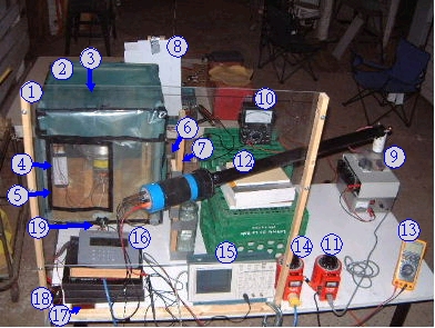
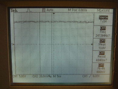
In the picture above: (1) a large piece of plexiglass in a wooden frame for sitting behind when looking through the sighting (in case the cylinders fly apart at high speed), (2) cylinders, phototachometer and thermometer mounted in test stand under the green plastic cover (digital scale is sitting on the table underneath all this), (3) phototachometer just visible under the green plastic cover, (4) thermometer - NEW, (5) clearer plastic added to make it easier to see inside - NEW, (6) marble to look for effects beside the cylinders, (7) the wood with sighting notch through the wood pieces for watching for marble movement (sighting notch is hidden behind probe), (8) white background for looking at marble through sighting notch, (9) high voltage power supply, (10) analog multimeter for measuring current through high voltage wire, the wire comes from the power supply on the right and goes through the plastic on the left to the stationary cylinder - NEW, (11) variac for power supply, (12) high voltage probe, (13) digital multimeter for measuring current from variac to vacuum cleaner motor which is under plastic cover - NEW, (14) variac for controlling vacuum cleaner motor speed, (15) oscilloscope, (16) control unit for digital scale (the digital scale is under the test stand), (17) playing card, (18) batteries and on/off switch for phototachometer, and (19) power and control wires (motor power, ground, phototachometer power).
The objective of this test was to spin the cylinder as fast as the vacuum cleaner motor could. This was too noisy and too dangerous to do in the living room of my appartment so I did it in a friend's barn instead. The temperature was -1 degrees C, and was probably my last opportunity to do it in the barn before winter started getting colder. The test ran into battery problems which made the test less than perfect but interesting results "may" have happened as descibed below.
The test went as follows:
- Turned on phototachometer only to realize I needed new batteries so we went and bought some.
- The scale was set to 0.0.
- The playing card was gently placed on top of the green plastic cover on the test stand. The scale reading changed over about 1 second from 0.1 grams to 1.7 grams and stayed at 1.7 grams, the weight of the card. The card was then removed and the scale went back to 0.0.
- The high voltage power supply was turned on and turned up to around 14kV. Any higher and arcing would occur between the cylinders. The scale continued to show 0.0. Having reread the patent I realized that they'd left the high voltage applied throughout the test so I left it on - NEW.
- The vacuum cleaner motor was turned on and the speed was slowly turned up to around 6000 RPM (see picture below). Throughout this the scale showed 0.0. At some point during high rotation I redid the playing card test with the same results. The phototachometer would show me the speed above 6000 RPM but if I turned the speed up above around 6050 RPM then the phototachometer would malfunction by starting to alternate random high values in the 9000 RPM to 11000 RPM range. As such there was no point in increasing the speed further.
Note that while the speed was around 6000 RPM I was frantically trying to get a good picture of the phototachometer readout and I bumped into the container with the phototachometer batteries (see 18 in the picture above). The container's case was open due to the changing of the batteries and the batteries fell out. In quickly putting them back in I put some in wrongly, and had a bad time of it. Basically in the confusion (remember I had a dangerous 6000 RPM spinning cylinder in front of me and my phototachometer was malfunctioning at higher RPM and it was below 0 degrees C) I didn't think to try a number of things and ended the experiment. For example, I forgot to check the marble for movement.
It wasn't until the next day (December 17, 2004) that I realized the reason for the phototachometer malfunction above 6000 RPM may not have been vibration or something wrong with the cylinder (I don't recall making any observations about it). The cause may have been due to some electromagnetic field or electromagnetically caused field coming from the rotating/stationary cylinder combination at high voltage. Had I thought of it then I would have turned off the high voltage and seen if the malfunction persisted. Instead I turned off the high voltage as I was ending the experiment and had already slowed down the rotation.
Some interesting observations:
- The temperature under the cover increased from -1 degrees C to 4 degrees C during the 5 minutes or so that the experiment lasted. As the scale reading remained at 0.0, the temperature rise was not enough to make the device bouyant enough to register on the scale (accuracy +/- 0.1 grams).
- At 6000 RPM the current draw of the motor from the variac was only about 5 amps as measured by the digital multimeter (13 in the picture above).
- With the analog multimeter (see 10 in the picture above) on the 100 microamp scale there was no noticable deflection. This means that the current through the high voltage wire was less than 1 microamp. This means that there was not much ionization at the cylinders.
|
First tests at 7700 RPM - Dec 20, 2004
Test 1 - reproducing >6000 RPM problem
I speculated that one possible reason the phototachometer was malfunctioning above around 6050 RPM was that electromagnetic fields created by the rotating charge of the cylinders were strong enough at that point to create interference. I tried it again but with the one difference that when I observed the malfunctioning, I turned off and discharged the high voltage power supply. I lowered the RPM to below 6000 so that the phototachometer displayed properly and then raised it again. The malfunctioning still happened. Note that as before the weight displayed by the scale remained at 0.0 and at no time did the marble move.
Test 2 - 7400 RPM, anomalous weight loss
I then removed the plastic cover and saw that the reflective tape had some black conductive grease on it from the conductive ground bearing. Possibly at high speed this interfered with the phototachometer. I replaced the reflective tape with a clean one and repeated the experiment.
This time I got up to 7500 RPM. I stopped going higher only due to the noise level in my apartment (it sounds like being beside a jet engine). While between 6000 RPM and 7000 RPM I tried discharging the high voltage power supply without turning it off in order to cycle the potential at the cylinders on and off quickly. This had no affect on the weight or the marble.
Then at some point while going from 7000 RPM to 7400 RPM the weight on the scale changed to show -2.4 grams but I wasn't watching the scale at the time the change occured. I slowly turned down the speed to see how that affected the weight change. The weight was slowly rising again (towards 0.0) but even at 5800 RPM it was still around -2.2 grams. While still turning down the speed I turned off and discharged the high voltage power supply but that didn't seem to change the rate at which the weight was returning to 0.0.
Only after having turned everything off did I think to check the thermometer. It was at 77 degrees C and the scale was still around -1 gram. After about 5 minutes the termperature was 75 degrees C and the scale was showing 0.0. After around fifteen minutes that temperature was 73 degrees C.
My first guess was that the test rig had shifted on the scale due to the high rotation speed and that had interacted with the feed wires to cause a change in weight. However, that would not account for the weight slowly and steadily returning to 0.0.
My best guess is that the temperature caused the entire completely enclosed and sealed test rig to act like a balloon with hot air in it. It may have become bouyant and that caused the weight loss.
Test 3 - 7700 RPM, anomaly at 7100 RPM/79 degrees C, 0.0 grams otherwise
I wanted to make an RPM/temperature/weight-loss table so I could do the math re bouyancy and expected weight loss. All did not go as planned. The following table is in order of time. The first entry was recorded first and the last was recorded last.
| RPM | Temperature (degrees C) |
Weight loss |
|---|---|---|
| 0 | 72 | 0.0 |
| 5900 | 75 | 0.0 |
| 6500 | 76 | 0.0 |
| 7100 | 79 | -0.5 |
| 7700 | 80 | 0.0 |
| 7100* | 79 | 0.0 |
* - Remember, this table is in time order so this last entry was after the 7700 RPM entry above it.
My guess is that the weight change to -0.5 was due to the test rig shifting on the scale and then restoring itself. Note that the seal in test 2 was not perfect. It had was open in 2 corners which would have allowed air to move down and out of the cover. I fixed this before test 3. That doesn't help explain the results though.
Conclusion after the day's testing
Getting up to higher RPM simply allows more stuff to happen (shifting of the test rig on the scale, higher temperatures). Further testing is required.
Reproduced Dec 20, 2004 anomalies proving no weight loss - Dec 22, 2004
I was able to reproduce the anomalous weight loss of Test 2 and Test 3 of the above Dec 20, 2004 experiments in such a way as to prove they were caused by the feed wires being twisted very slightly causing a lessening of the weight on the scale that slowly went away.
I prepared everything for a new experiment run. As a last step, I zeroed the scale and then lifted the scale's control unit to allow the feed wires to relax to a stable position. In doing so I instead shifted them and the test rig sideways a little. The scale read -2.4 grams.
|
Suspecting that the previous anomalous results were due to sudden twisting of the test stand sitting on the scale, where the twisting was caused by my unevenly accelerating the motor while at very high speed (>7000 RPM), I left everything alone and watched. After about 1 minute the scale read -2.2 grams and about 1 minute later it read -2.1 grams. I then stepped to beside the table where I would be to check the temperature as I did on Dec 20, and noticed that the scale reading fluctuated downward around 0.1 grams. The floor is a hardwood floor with some very small warping of the floor boards in places, including beside the table. If I sat back down in front of the plexiglass it would usually stabilize down by 0.1 grams. So now it was at -2.0. This was really just duplicating the types of movements I did on Dec 20. If I went away for about 5 minutes and returned, the reading would be down by another few tenths of a gram. After a similar amount of time to that of Dec 20, the scale read 0.0. If I walked by the table, the scale would sometimes fluctuate between 0.0 and 0.1 but would always settle at 0.0. It did not go any further down on its own.
This means that the anomalous results were due to my turning the speed up unevenly. At above 7000 RPM, doing so can cause the test rig that is sitting on the scale to twist. This upsets the feed wires a bit such that there is some tension in them. That tension results in the test rig being supported a little by the feed wires. Over time, gravity relieves this tension and the test rig sits as it was before the twisting occurred. Also, walking on the slightly warped floor boards beside the table that everything is sitting on causes a movement in the table and hence the things sitting on it, causing the tension to be relieved a bit. Once the tension is completely relieved, the scale reads 0.0 and stays there.
Smoke test and 8400 RPM - Dec 23, 2004
I decided to look for effects on gravity above the cylinders. Taking a page from Podletknov, I spun it up as before but this time blew smoke from a Colts small cigar (which I have on hand for these purposes) over the top of the test rig. I did it:
- with nothing turned on,
- with the cylinder not rotating but with the high voltage turned on, and
- at various points as I accelerated the device with high voltage turned on: 3100 RPM, 5400 RPM, 7100 RPM, 8400 RPM.
At no time did I see any upward flow of the smoke that I didn't see with 1 above.
Note that in this test I decided to turn it up all the way to 8400 RPM. The current draw by the motor was still only in the 5-6 amp range. Weight change occured on the scale but only when I was accelerating it too fast. If I left it steady for a few seconds, the weight change would go away as the twisting reset itself.
Conclusion
This configuration of cylinders, when charged with around 14kV and rotated up to 8400 RPM, produces no weight change.
As the cylinders have different dimensions than the ones in the patent it is worth it to replicate them more exactly and produce a less rigorous experiment to continue trying to replicate their results. By less rigorous, I mean to try without the large wooden base and the plastic cover, anticipating that their results may have been caused by a wind directed by the polarity of the charge. If weight change is detected then the rigor can be added back to see if the weight change is eliminated.
