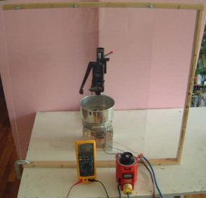
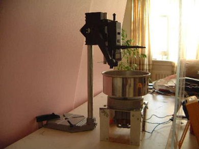
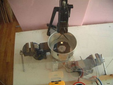
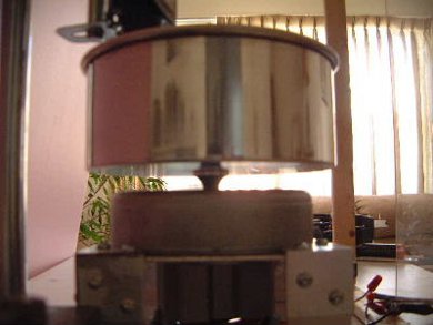
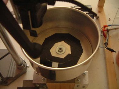
Rotating Charged Cylinder Mk 1 - Construction 1
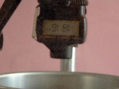
Using this arrangement, at about 1820 RPM the unit begins to move
across the table due to vibration. It is still quiet at that point.
I've managed to get 3400 RPM at 3 Amps. The
reason this is a limit is that this is the size of the fuse in my variac.
Due to vibration on the table it is very noisy at this speed.
Test setup. The wooden frame holds a sheet
of lucite for protection. At bottom are a multimeter for measuring
current and a variac for controlling speed and watching voltage.
 |
|
Side view of test setup. The
vacuum cleaner
motor is at the bottom. Mounted on the motor is a pot. This is
the cylinder that will spin and be charged with one polarity. Above
the pot is a phototachometer which displays the speed as RPM.
 |
|
Output of the phototachometer. The output is
in RPM and is upside down. The reading in this picture is 1816 RPM.
 |
|
At aproximately 1820 RPM the motor and pot begin
to move across the table due to vibrations caused by the imperfect
arrangement of the pot on the motor shaft or by the pot not being level.
I've put a vice on either
side of the motor frame to hold it in place.
 |
|
Bottom view showing the pot attached to the motor
shaft.
 |
|
Top view showing the pot attached to the motor
shaft. Two rings of black electrical tape surround the center. On that
tape, in the bottom you see a grey square. This is the reflective
tape for the phototachometer to read. The black tape is for contrast
so that the phototachometer works properly. In the photo above
you can see the spot of light that the phototachometer projects.
 |
|
The Stationary Electrode
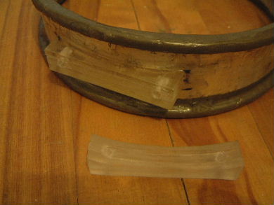
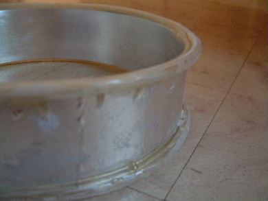
The stationary electrode was made by getting a fabrication shop to
roll two alluminum strips of metal into two 3/4 cylinders. I then
cut each to the length of a 1/2 cylinder and taped them together
using aluminum tape to make a single cylinder.
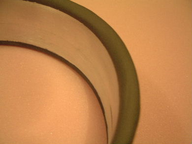
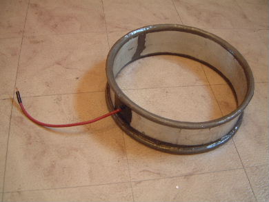
The next step was to make the edges be rounded while also ensuring
that the electric field would not be densest at the edges. To do this
I used resin to glue 1/4" diameter nylon tubes to the outside top
and bottom edges of the cylinder. To make the result conductive,
I sprayed them with nickel spray. The spray I used was
Super Shield Conductive Nickel Coating from M.G. Chemicals.
I then attached a wire and coated
the whole thing in resin. The pictures below illustrate this.
The nylon tube taped in place for one end of
the cylinder. Aluminum tape is also visible sticking up from the
inside of the cylinder prevent too much resin from dripping into
the cylinder.
 |
|
After pouring the resin to glue the tube in place
and to provide rounding of the edge.
 |
|
The resin and tube coated with conductive nickel
paint.
 |
|
The end result with wire attached and the whole
thing coated in resin.
 |
|
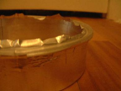
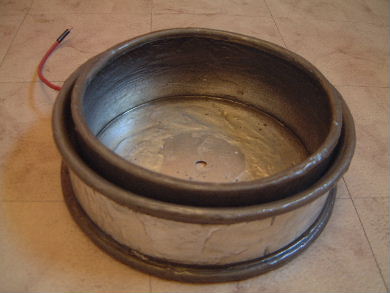
The Rotating Electrode
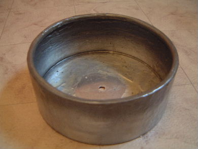
The original rotating electrode was a cooking pot with a lip sticking
outward at the top. I cut the lip off but was now left with a sharp edge.
To get rid of the sharp edge I did the same sort of thing as illustrated
for the stationary electrode as described above but put the nylon tube
on the inside instead.
The resulting electrode with inwardly curved
top edge.
 |
|
The Electrodes together
Here the electrodes are shown together.
 |
|
To mount the stationary cylinder to the test stand
I had to add "Lucite" acrylic mounting pieces to either side.
 |
|
rimstar.org
|
Back to Rotating Charged Cylinder Mk 1.
If you have any suggestions of information to add, advice, corrections, ...,
please send email to:
|