Stabilizing BB-8 (v2) with an intertial measurement unit/gyros
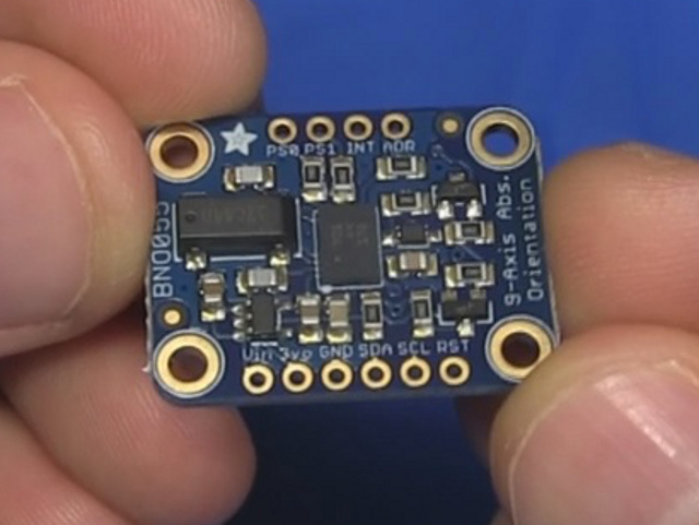
At first my BB-8 (v2) wobbled back and forth quite a bit whenever it stopped and so to fix this I added an inertial measurement unit (IMU), the BNO0355 from Adafruit. This is connected to the Arduino and tells the Arduino the orientation of the IMU board, and hence the orientation of the BB-8 drive system that it's mounted on. The Arduino uses that information to turn on the motors in the direction needed to counter the wobble.
You can see it in action in the video below.
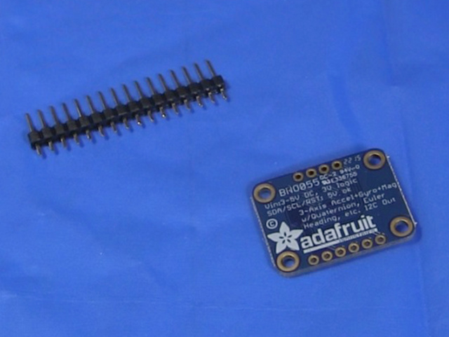
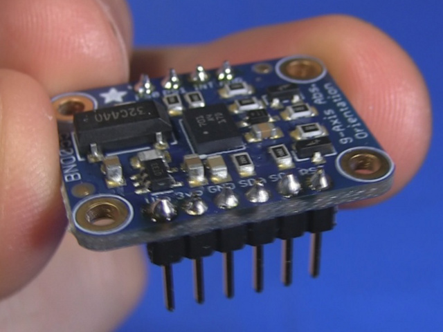
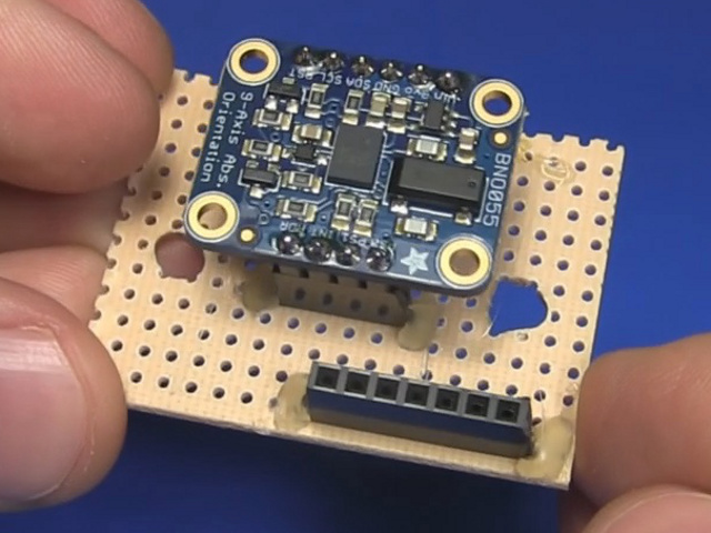
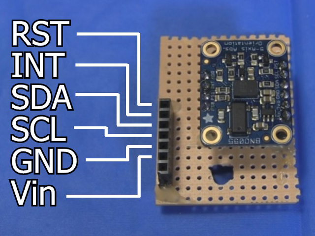
As shown below, the board comes with these two parts, the BNO055 board itself and a bunch of male pin headers (you can buy male and female pin headers from Adafruit. First I solder pins to the board. I do that by putting the pins in a breadboard and sitting the board on top of the pins. That way the breadboard acts as a heatsink to reduce the chance of overheating the board. My soldering iron is on the 40 watts setting. I touch the iron's tip to the pin and board's metal ring for only around 2 seconds and then briefly touch it with the solder. Be careful not to put too much solder and connect more than one pin together. Very little solder is needed.
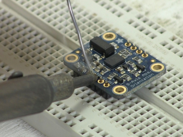
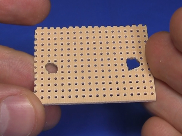
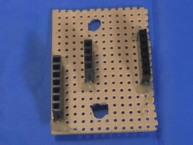
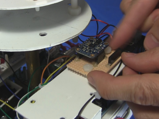
As you can see above, there is no place to connect the wires from the Arduino to the board or the pins without soldering. I prefer to plug in my wires. So, as shown below, I cut up some perboard and drill holes in it for mounting on BB-8's drive system. I then plug some female pin headers into the boards pins. That way they're lined up nicely while I hot glue those female headers to the perfboard.
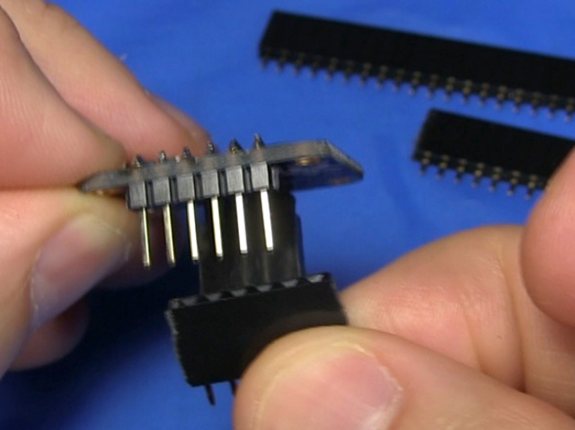
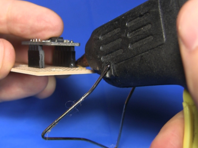
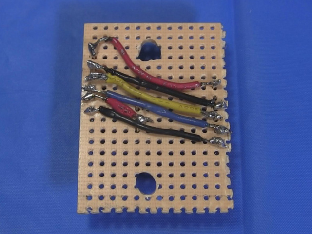
I also hot glue on a separate seven pin female header which is where I'll be plugging in the wires going to the Arduino. I then solder wires from pin headers that the board will be plugging into, to the seven pin headers. I do the soldering without the board plugged in so as to not damage the board from heat.
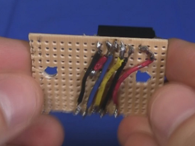
Below is how the wiring is done as well as the pinouts for connecting. Notice that I've provided two Vins holes. Why I did that is explained below. Note that I'm not going to use the board's reset or interrupt pins but I make them available on the seven pin header in case I want to later.
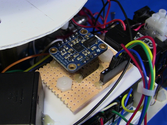
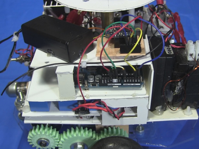
Since the wires are short, I remove the Arduino's battery case and put some lightweight nylon nuts, bolts and washers for mounting the board. I then put the board in place.
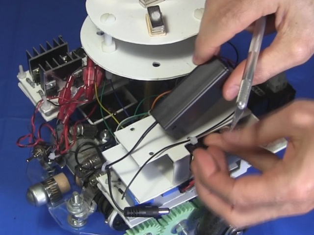
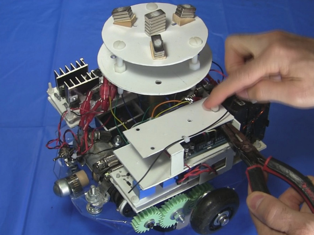
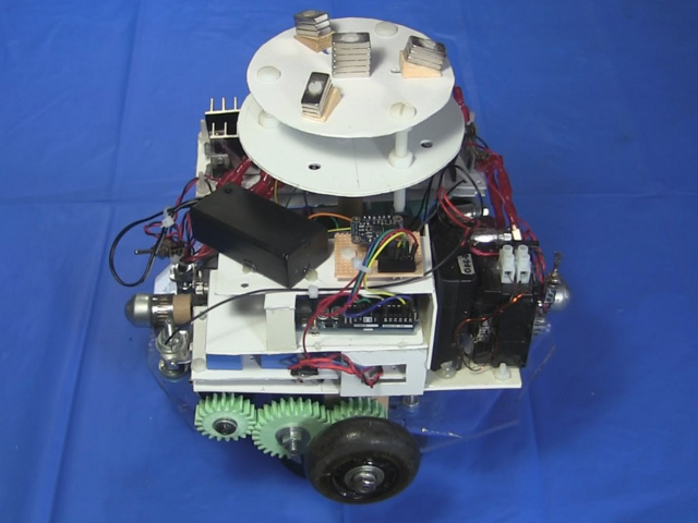
Below you can see the board in place and wired up, and the new position of the battery case beside it (angled a bit so that it won't collide with the inside of BB-8's ball.) Below you can also see the wires labelled before they were tie strapped together.
Notice that the Arduino has only one 5 volt pin hole. But I need one for the BNO055 IMU board and another for the RC controller board that's installed below the Arduino. That's why I put two Vin holes in the seven pin header. One goes to the Arduino's 5 volt pin and the other goes to the RC controller board to give it power.
The software
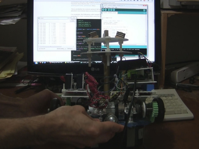
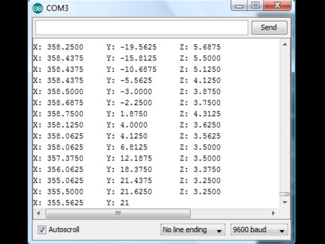
The wobble I want to fix is the back and forth wobble that happens immediately after the motors are turned off. The BNO055 IMU board tells me all sorts of information, including the tilt angles in the X, Y and Z orientations. At first I don't know which one is useful since I just arbitrarly mounted the board. So as part of the BNO055 installation information on Adafruit's website, they also give a sample program that displays all three angles to the serial board. I simply install it on the Arduino and manually tilt the BB-8's drive system in the back and forth direction. That shows me that it's the Y-axis angle that's changing.
With that sample code as a basis I add pieces to my BB-8 program and fine tune it until I have something that works well. The code is given below.
The main part is in the loop() function. The first part is the usual checking for commands from the remote control to turn on and off motors. I then added a new section to handle the wobble whenever at least one of the motors was previously on but has just been turned off. If that's the case then I put the loop in a state that I call STATE_IMU_LEVELING. Whenever the loop() function is called and I'm in that state then I keep checking the Y-axis angle and turning on and off motors to get it to less than LEVELLED_ANGLE degrees and no longer changing.
LEVELLED_ANGLE is defined near the top of the code. Check the code for the value I settled on though I tried 3 degrees, and then 5 and then 7. Basically I kept adjusting it by trying to minimize the amount of activity the motors had to do while having it end up standing fairly straight up.
Note that if at any time the remote control sends a signal to turn on a motor (i.e. the operator decides to get the BB-8 moving again) then the code abandons all levelling activity and goes back to normal. That's done simply by having the remote control code be above the levelling code in the loop() function and setting the state to STATE_NORMAL.
/* BB-8 (v2) Arduino code August 10, 2016 - Added BNO055 Inertial Measurement Unit (IMU) to run motors to cancel any wobble after the motors are remotely stopped. July 6, 2016 - Switched pins 5 and 6 to 3 and 11 to use the lower PWM frequency (Arduino UNO). This is because I'm using brushed motors, and unlike with brushless motors, the higher the frequency, the worse it is for brushed motors. Full details about this BB-8 droid can be found at: http://rimstar.org/science_electronics_projects/bb-8_star_wars_droid_v2.htm Drive motor circuits -------------------- The two motors are driven independently and so there are two Radio Controls (RC), one for each motor. Each one can turn in two directions. The RC controls are just on/off switches so there is no speed control from that end and none is done in software either other than PWM, but it never changes. A circuit exists between the RC receiver and the Arduino to give the Arduino the following inputs: rc1FwdPin - a digital pin indicating that motor 1 should be turned on in the _forward_ direction (HIGH) or off (LOW) rc1RvsPin - a digital pin indicating that motor 1 should be turned on in the _reverse_ direction (HIGH) or off (LOW) rc2FwdPin - an analog pin indicating that motor 2 should be turned on in the _forward_ direction (value > 0) or off (0) rc2RvsPin - a digital pin indicating that motor 2 should be turned on in the _reverse_ direction (HIGH) or off (LOW) Note that one of the pins above (rc2FwdPin) is an analog pin simply to save on the cost of one more relay. The relays were needed as using analog for all of them meant problems with common ground in the RC receiver. The two motors are then controlled using two H bridge circuits. Controlling each H bridge circuit is done by the Arduino by turning on and off transistors using digital pins. There are two transistors for each H bridge, one for each direction the motor can turn. The motors each can turn counterclockwise (CCW) or clockwise (CW) depending on which transistor is turned on. Just which direction is called foward and which is reverse is chosen arbitratily since the BB-8 doesn't really have a forward or reverse direction. A piece of masking tape on the drive plate has "FWD" written on it to select one direction as forward. Pulse Width Modulation (PWM) is done to the above mentioned pins for speed control. The variables bridge1PWMduty, for motor 1, and bridge2PWMduty, for motor 2, have the PWM values. 0 turns the transistor/motor off. The pins are: bridge1CWPin - digital pin for motor 1 clockwise bridge1CCWPin - digital pin for motor 1 counter clockwise bridge2CWPin - digital pin for motor 2 clockwise bridge2CCWPin - digital pin for motor 2 counter clockwise Note that since it's a tank drive, to go forward one motor must turn clockwise while the other motor turns counterclockwise. */ /*- stuff for the IMU ----------------------------------------*/ #include#include #include #include Adafruit_BNO055 bno = Adafruit_BNO055(55); // number of degrees the angle is allowed to be from 0 to be // considered level #define LEVELLED_ANGLE 9.0 // was 7.0 but 9.0 seems to work better float prevorientation = 361.0; /*- end stuff for the IMU ------------------------------------*/ /* states for the loop() below */ #define STATE_NORMAL 0 #define STATE_IMU_LEVELING 1 int state; /* stuff for motor 1 */ int isMotor1On = 0; // motor 1 is off = 0, on = 1 int bridge1CWPin = 9; // digital pin 9 for PWM int bridge1CCWPin = 10; // digital pin 10 for PWM int rc1FwdPin = 7; // digital pin 7, relay's switch int rc1RvsPin = 8; // digital pin 8, relay's switch int bridge1PWMduty = 48; // duty cycle for H bridge 1 // (a value of 25 blew a 1 amp fuse and // 48 blew a 3 amp fuse but not a 5 amp fuse.) /* stuff for motor 2 */ int isMotor2On = 0; // motor 2 is off = 0, on = 1 int bridge2CWPin = 3; // digital pin 3 for PWM int bridge2CCWPin = 11; // digital pin 11 for PWM int rc2FwdPin = 0; // analog pin 0 int rc2RvsPin = 4; // digital pin 4, relay's switch int bridge2PWMduty = 48; // duty cycle for H bridge 2 // (a value of 12 blew a 1 amp fuse and // 48 blew a 3 amp fuse but not a 5 amp fuse.) void turnMotor1Off() { analogWrite(bridge1CWPin, 0); // off analogWrite(bridge1CCWPin, 0); // off isMotor1On = 0; } void turnMotor1CW() { analogWrite(bridge1CWPin, bridge1PWMduty); // PWM duty cycle analogWrite(bridge1CCWPin, 0); // off isMotor1On = 1; } void turnMotor1CCW() { analogWrite(bridge1CWPin, 0); // off analogWrite(bridge1CCWPin, bridge1PWMduty); // PWM duty cycle isMotor1On = 1; } void turnMotor2Off() { analogWrite(bridge2CWPin, 0); // off analogWrite(bridge2CCWPin, 0); // off isMotor2On = 0; } void turnMotor2CW() { analogWrite(bridge2CWPin, bridge2PWMduty); // PWM duty cycle analogWrite(bridge2CCWPin, 0); // off isMotor2On = 1; } void turnMotor2CCW() { analogWrite(bridge2CWPin, 0); // off analogWrite(bridge2CCWPin, bridge2PWMduty); // PWM duty cycle isMotor2On = 1; } void turnMotorsOnFwd() { turnMotor1CCW(); turnMotor2CW(); } void turnMotorsOnRvs() { turnMotor1CW(); turnMotor2CCW(); } void setup() { pinMode(bridge1CWPin, OUTPUT); pinMode(bridge1CCWPin, OUTPUT); pinMode(bridge2CWPin, OUTPUT); pinMode(bridge2CCWPin, OUTPUT); turnMotor1Off(); turnMotor2Off(); Serial.begin(9600); // for sending debugging messages /* initialise the BNO055 IMU sensor */ if (!bno.begin()) { /* there was a problem detecting the BNO055 ... check your connections */ Serial.print("Ooops, no BNO055 detected ... Check your wiring or I2C ADDR!"); while(1); } delay(1000); bno.setExtCrystalUse(true); } boolean debounce(boolean last, int switchPin) { boolean current = digitalRead(switchPin); if (last != current) { delay(5); current = digitalRead(switchPin); } return current; } int rc1FwdValPrev = LOW; int rc1RvsValPrev = LOW; int rc2FwdValPrev = 0; int rc2RvsValPrev = LOW; void loop() { int rc1FwdVal = 0; int rc1RvsVal = 0; int rc2FwdVal = 0; int rc2RvsVal = 0; int wasMotor1On, wasMotor2On; sensors_event_t event; wasMotor1On = isMotor1On; wasMotor2On = isMotor2On; /* * Handle Motor 1 */ // get the relay's switch position rc1FwdVal = debounce(rc1FwdValPrev, rc1FwdPin); //Serial.print("1F:"); //Serial.println(rc1FwdVal); if (rc1FwdValPrev != rc1FwdVal) { // the switch position changed rc1FwdValPrev = rc1FwdVal; if (rc1FwdVal == HIGH) { // the relay was turned on turnMotor1CCW(); } else { // the relay was turned off turnMotor1Off(); } state = STATE_NORMAL; } // get the relay's switch position rc1RvsVal = debounce(rc1RvsValPrev, rc1RvsPin); //Serial.print("1R:"); //Serial.println(rc1RvsVal); if (rc1RvsValPrev != rc1RvsVal) { // the switch position changed rc1RvsValPrev = rc1RvsVal; if (rc1RvsVal == HIGH) { // the relay was turned on turnMotor1CW(); } else { // the relay was turned off turnMotor1Off(); } state = STATE_NORMAL; } /* * Handle Motor 2 */ rc2FwdVal = analogRead(rc2FwdPin); //Serial.print("2F:"); //Serial.println(rc2FwdVal); if (rc2FwdVal > 0 && rc2FwdValPrev == 0) { turnMotor2CW(); rc2FwdValPrev = rc2FwdVal; state = STATE_NORMAL; } else if (rc2FwdVal == 0 && rc2FwdValPrev > 0) { turnMotor2Off(); rc2FwdValPrev = 0; state = STATE_NORMAL; } // get the relay's switch position rc2RvsVal = debounce(rc2RvsValPrev, rc2RvsPin); //Serial.print("2R:"); //Serial.println(rc2RvsVal); if (rc2RvsValPrev != rc2RvsVal) { // the switch position changed rc2RvsValPrev = rc2RvsVal; if (rc2RvsVal == HIGH) { // the relay was turned on turnMotor2CCW(); } else { // the relay was turned off turnMotor2Off(); } state = STATE_NORMAL; } /* * Handle any wobbling after motors have been turned off remotely. */ if (state == STATE_NORMAL && ((wasMotor1On || wasMotor2On) && (!isMotor1On && !isMotor2On))) { // Either of the motors was on but now both are off. // Start interacting with the IMU to cancel any wobble. state = STATE_IMU_LEVELING; // We'll start processing the state on the next time loop() // is called since we just did some motor stuff and want to // wait. } else if (state == STATE_IMU_LEVELING) { bno.getEvent(&event); //uncomment for debugging //Serial.print("\tY: "); //Serial.print(event.orientation.y, 7); if (abs(event.orientation.y) <= LEVELLED_ANGLE) { // the angle is small so stop any motors turnMotor1Off(); turnMotor2Off(); if (prevorientation == event.orientation.y) { // we're no longer wobbling, go back to normal state = STATE_NORMAL; prevorientation = 361.0; } // else // we may still be wobbling toward the other side and // would need to correct for that, so we stay in // the STATE_IMU_LEVELING state } else { // if the Y-axis is negative then go backward // if the Y-axis is positive then go forward if (event.orientation.y < -LEVELLED_ANGLE) turnMotorsOnRvs(); else turnMotorsOnFwd(); } prevorientation = event.orientation.y; } delay(50); }
Video - Making BB-8 (v2) - Adding Gyro/BNO055 IMU - Part 4
Here's my video showing how I added the IMU and showing it in action.
