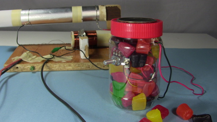
Homemade/DIY amplifier for loud speaker
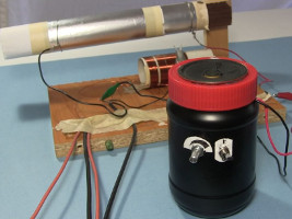
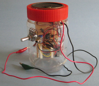
This is a homemade amplifier that's powered by a 9 volt battery, has an on-off switch and an audio tapered volume knob (potentiometer) for more natural volume control. It makes use of the LM386 amplifier chip, though I used the equivalent NTE823. Some of the things I've used it for include crystal radios, laser communicator, Arduino speech synthesizer, a photophone and much more. As you can see below, I package it up in a jar usually painted black and with the speaker in the jar's cover, though in the laser communicator I built it into the laser communicator itself and use it for amplifying the signal going to the laser.
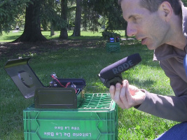
Watch the video below to hear it in action.
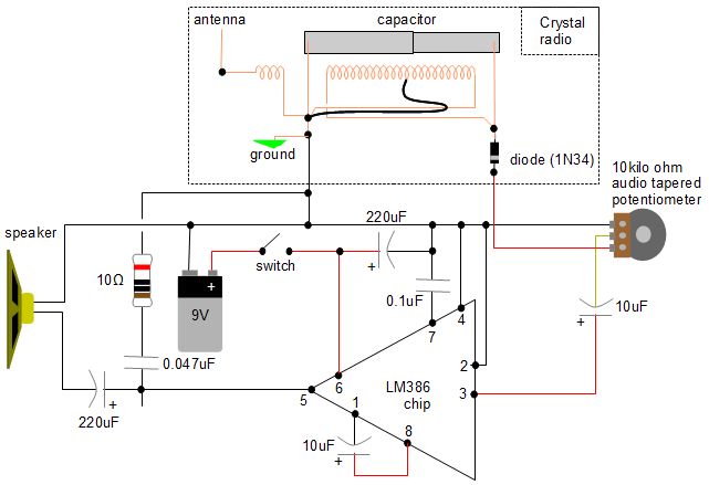
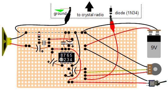
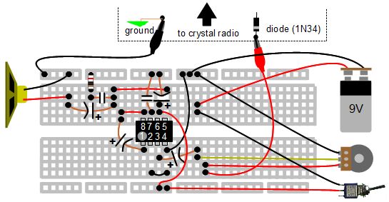
The following is the circuit I used. I first got it from the book "Radio Receiver Projects You Can Build" by Homer L. Davidson and then found the same general circuit diagram in this pdf document describing the LM386 chip on Texas Instruments' website.
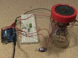
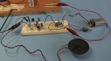
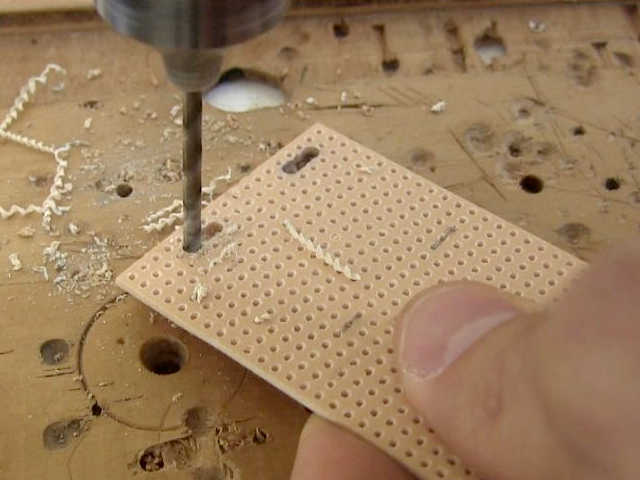
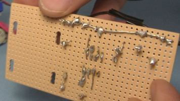
I first made and tested the circuit on a breadboard and then moved the components over one-by-one to a perfboard, soldering them together on the back. The layout I used is given in the diagram below in case you want to do this too.
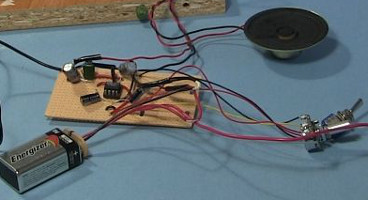
And below is how I laid it out on the perfboard. See the circuit diagram above for how the parts should be soldered together on the back. The layout I used when I put it on the breadboard is given further down below.
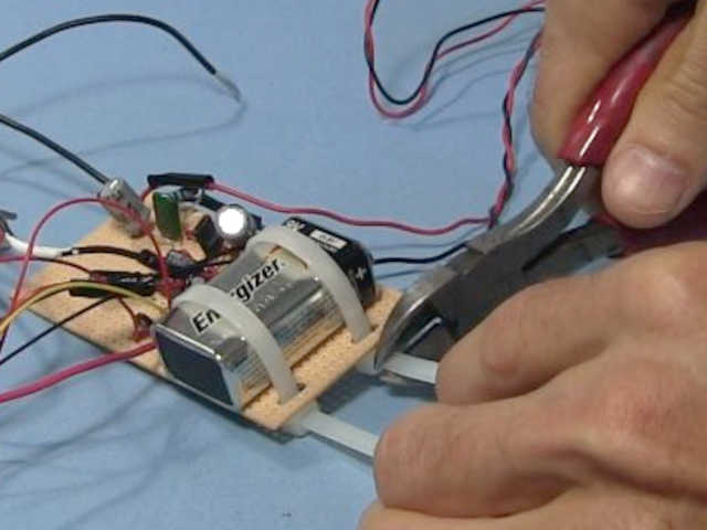
The 9 volt battery was attached to the perboard using two tie straps. They were put on loosely enough to make it easy to slide the battery in and out for replacement while being tight enough to hold it in place.
If you prefer to make it on a breadboard then here's the layout I used when prototyping.
Video - How to Make a Crystal Radio Amplifier for Speaker
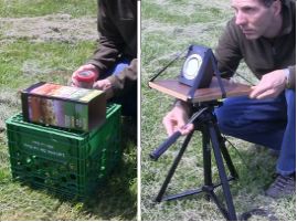
Below is a video I made that not only demonstrates this amplifier in action but also goes through step-by-step how to make it.
