Wireless transmission of electricity (DIY)
This is a simple circuit for wirelessly transmitting electricity, making use of the popular joule thief circuit. This trick was invented by slider2732 and introduced in his video Simple Wireless Electricty System.
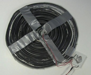
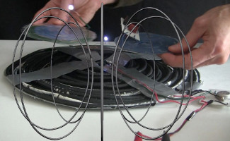
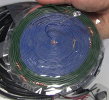
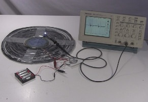
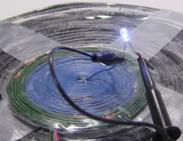
It consists of the joule thief circuit and two big flat coils, wound in a spiral together as shown below. The big flat coils are where the energy is transmitted from. For receiving the energy and turning it into electricity, we make a smaller flat coil and attach whatever we want to power to it. Below we have three receiver coils, two powering LEDs and one powering a little circuit with a piezo buzzer making a sound.
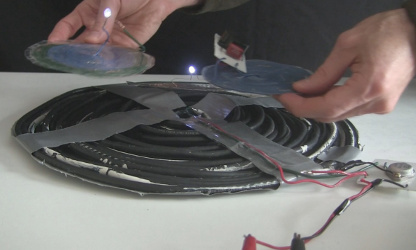
Listed in order of increasing transmitting power, I've powered it off a single AA battery, four AA batteries connected in series and my homemade 24 volt DC power supply set to output around 5 volts. The batteries and power supply are not shown in the above photos but that's where the black and red wires go to that end at the edge of the photos. With these big transmitting coils, the AA batteries run down pretty fast and should last longer with a smaller diameter set of transmitting coils. Lithium-ion batteries should last longer with these big coils.
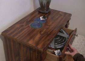
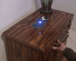
The energy is transmitted as a fluctuating electromagnetic field, which is not blocked by things like cardboard or wood. So below you can see I've put the transmitting coils in a desk drawer and am powering the receivers on top of the desk.
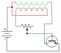
Here's the circuit diagram. If you're familiar with the joule thief circuit you'll notice that the only change is that the two coils wrapped around a ferrite toroidal core have been replaced with two coils wound side-by-side in a spiral.
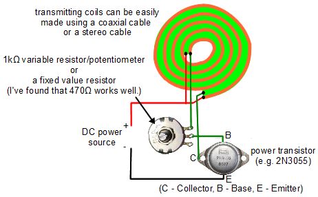
My transmitting coils are made by winding a coaxial cable. I think is was around 45 feet and was a complete cable with connectors on either end that I cut off. Another easy way to make them is to use speaker wire or any cable that has two conductors in it. The transistor will get hot if you put enough current through it. In the photos above, the transistor didn't get hot so I didn't bother adding a heat sink.
The receiver coils
To receive the transimitted energy you need to make receiver coils. As shown each one is simply wire wound in a spiral. The bigger the diameter, the more energy they'll capture. They must be wound in the same direction as the transmitting coils. In the photos below you can see that I had to connect many wires together to get enough length to make a big diameter.

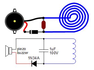
Below are the circuit diagram and schematic for the piezo buzzer receiver. It was figured out by trial and error and with the parts I happened to have, so likely other capacitor values and diodes may work as well or better. Note that the capacitor cannot be a polarized capacitor, like an elecrolytic capacitor or supercapacitor (though the capacitance of a supercapacitor would be too high anyway.)
Spreadsheet for calculating receiver coil dimensions
The following is a spreadsheet to do calculations that'll help you figure out how much wire you'll need, how big your coils will be, how many turns there will be, and so on.
wireless_trans_electricity_coil_calcs.ods - OpenOffice Calc format
wireless_trans_electricity_coil_calcs.xls - Excel spreadsheet format
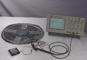
Measurements
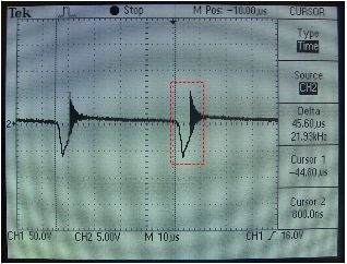
The first measurement was for input voltage when powering a single receiver coil with an LED. Given that I was using 4 1.5 volt AA batteries in series for a fully charged total of 6 volts, the 5 volts makes sense. The 22kHz cycle is expected given that the joule thief circuit is an oscillating circuit.
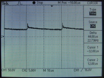
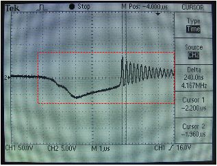
The next measurement was for output voltage across the legs of the LED. Below, you can see the 22kHz cycle but also that the second half of each cycle consists of a dampened wave at 4.1MHz.
Video - Wireless Transmission of Electricity/Joule Thief - How it Works
Below is a video I made demonstrating this wireless transmission of electricity in action.
Video - How to Make Wireless Transmission of Electricity/Joule Thief
In the following video I show step-by-step how to make this wireless electricity transmission system.
