The Linden experiment was performed by Paul Baumann for two visitors.
They then described it to someone who wrote it in a letter. The following
is the text from that letter that describes the experiment. The information
is therefore second hand and taken from memory. As such the details
may not be exact. The diagrams below the text were on the same page
of the letter that the text was on. The names have been replaced with
"____" at the request of the letter writer. Paul Baumann's followers call
him "Vatti" (daddy).
|
The two engineers asked Vatti how the machine was working, and he started to explain the
"principle." He said that in Nature, there are very fine particles and all
going at random (fluctuation) and at an incredible speed. To control
and have an advantage of this fact, one must find a means to "rectify" the
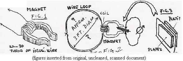
flux.... He took a U-shaped magnet from the drawer and asked ____ to wind a
normal installation wire on to the middle of the U-shape (Fig.1). The ends
of the wire were kept at a certain length (____ said, maybe 3 feet each.) The
very ends were stripped off the insulation and galvanicly connected, thus
forming a loop. This was placed on the table (what was underneath?) (Fig.2).
Paul Baumann took two small metal plates and put them together
with some paper in between (Fig.3) This was like a flat capacitor.
Now he placed this "sandwich," holding it with his fingers in the "jaw"
of the Magnet, i.e. between the poles. After a short trial to find the best
position, he asked the engineer to put the probes of his voltmeter onto
the plates. ____'s surprise: there was a voltage of 700 volts indicated!
P.B. said, "When you understand this, you know how it works. This is just
the beginning."
Back in their own laboratory, ____ tried to repeat the experiment.
I also tried to get such an output. No result!
I have asked ____
whether he had his meter in position "Resistance" and he had measured
Vatti's skin resistance. He says that he was
definitely sure what he was doing. He added to this, "The relative high
voltage seemed to drop slowly when I had the instrument on the plates."
(This would correspond to the normal experience when an Owm-meter's probes
are touched with both hands (progressive polarization of the skin surface
due to the applied voltage/current).
|
Replication attempts
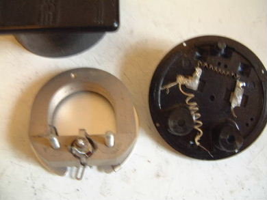
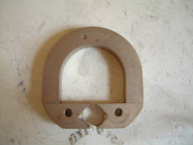
Linden Experiment Magnet
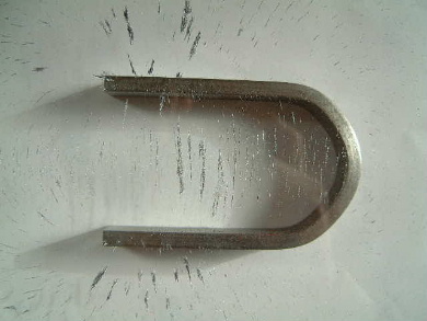
The type of magnet used in the Linden experiment was like a meter magnet
and as such, anyone trying to replicate it should try with one like it.
Note also that since a meter magnet may have been used, physical contact between the
plates and the magnet itself may be necessary.
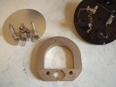
The type of magnet used in the Linden Experiment.
The dimensions of this one that I found are 56mx57mmx10mm.
 |
|
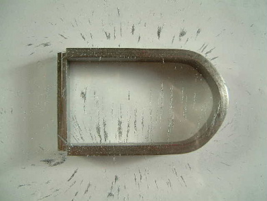
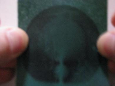
The same magnet looked at through magnet viewing film.
 |
|
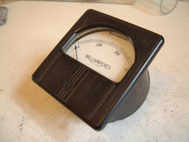
I found my meter magnet by purchasing an old meter on ebay.
It's important that it be old, possibly
made before 1980. Meters nowadays seem to all use a pair of small neodimium
magnets and my understanding is that neodimium magnets didn't exist before
the 1980s. Also, one of the meters I purchased on ebay had a range of 0 to
100 amps and did not have the desired type of magnet, possibly because the
current from the source was so large that such a magnet was not needed.
The meter that I found that contained the desired magnet offered a milliampere
range. The ebay seller also pointed out that the meter case was made of
bakelite, a type of plastic use in the first half of the 20th century, further
guaranteeing its age.
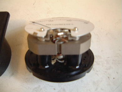
Testing for resistance with a digital multimeter I found that the entire
magnet was made of an electrically conductive material, the resistance from
any point on the surface to any other being around 0.2ohms. Also, the external
magnetic field was fairly weak everywhere except in the area of the gap, where
it was very strong.
Removing the magnet from the meter.
|
|
|
|
|
|
Shape of magnetic field between legs of U-shaped/horseshoe magnet
I'd always thought that the magnetic field lines between the legs of a
U-shaped/horseshoe magnet run parallel to the legs. Back in 2000, I tested
this by placing a U-shaped magnet under a sheet of plexiglass and placing
iron filings on the plexiglass.
The following resulting photos show that the field lines on the insides of
the legs go directly from one leg to the other leg. This is good since it
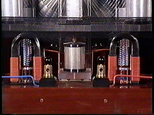
matches what would be the case with the above meter magnet. It also jibes
with the plates in between the legs of the magnets in the 3kW machine being
oriented parallel to the legs matching what is shown in the Linden experiment
above.
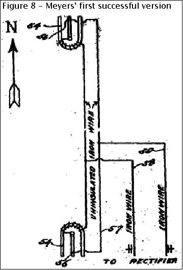
Linden Experiment and the Roy Meyers device
Note the similarity between the Linden experiment and the
Roy Meyers device. Might the
Methernithans have studied, replicated and improved on the Roy Meyers device?