These are attempts to replicate the Linden Experiment
and figure out if the horseshoe magnets used in the testatika in general are
tapping an energy source. All these experiments involve the use of my
POS400+ UHF chip oscillator circuit
to do pulsing of the magnetic field. The dates given are approximate as sometimes
they were done over multiple days.
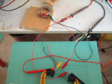
Dec 6, 2007 - Linden experiment with meter magnet driven by POS400+ oscillator
First I tried the Linden experiment but using the POS400+ oscillator to pulse
the magnet. I adjusted the control voltage in steps of 0.1 volt from 4.0 volts to
12.0 volts. As the graph at the bottom of my lecher
line tests show this is from around 280MHz to 425MHz. The magnet was lined up with
it's south pole on the geomagnetic north side and the north pole on the geomagnetic
south side.
As previously discovered during my first series of
Linden experiment tests holding the capacitor with the fingers of one hand
put a voltage of 1.5 volts across the capacitor. At no time
was any additional voltage seen.
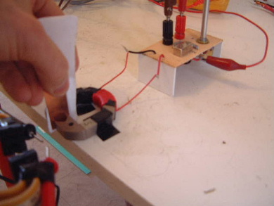
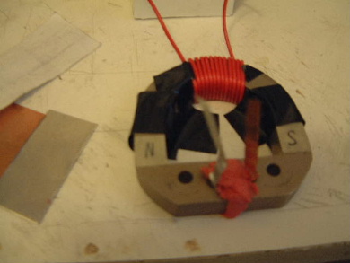
Putting the capacitor in place between the poles.
 |
|
Applying the voltage test probes.
 |
|
I also checked for induction to find the control voltage that gave the most induction
by putting a UHF diode, NTE503, between the probes of my multimeter and looking for
when the voltage on the multimeter would be highest. Highest induction turned out
at a control voltage of around 4.2 volts, corresponding to around 297MHz.
The diode.
 |
|
Testing for induction. This gave around 0.25V on the multimeter.
 |
|
Testing for voltage. Touching one leg of the diode in this area on
the magnet gave an induced voltage of around 0.42V. Comparable voltage was found in
other locations too.
 |
|
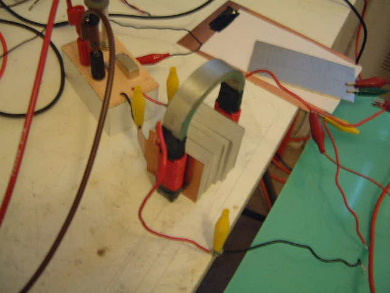
Dec 9, 2007 - Horseshoe magnet with DC voltage on plates between legs
I next tried a 4" tall horseshoe magnet with a DC voltage applied between the legs.
See the photos below.
0VDC to 30VDC was applied to the plates sandwiched between the legs and pressing
against the coils wrapped around the legs. The coil around the top of the
magnet was pulsed by the POS400+ oscillator. Tests were made with the bottom
ends of the leg coils in electrical contact with the magnets and without.
The result was hoped to be a voltage
across the coils wrapped around the legs. No such voltage was seen.
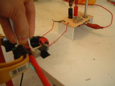
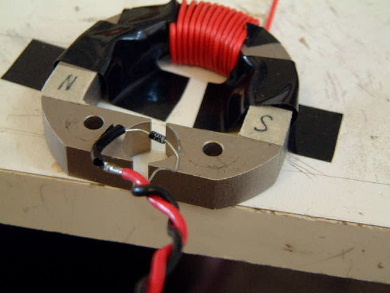
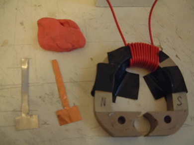
Dec 16, 2007 - Meter magnet with plates touching poles to variable capacitor
I next tried making a more complete electrical contact with the poles of the
meter magnet by pressing two plates against them, using plasticine to hold
them in place as the following photos show.
I then looked for the control voltage where there was the greatest induction,
this turned out to be around 333MHz. I calculated the inductance of the coil
wrapped around the magnet to be around 9.072mH which meant the inductive
reactance would be 1.898x10⁻⁷ohms. Assuming the same for capacitive
reactance, I calculated a resonant capacitance of 251.8pF. I next calculated
the required plate area assuming a paper dielectric, coming up with around
27.2square centimeters. I arranged such a capacitor and repeated the Linden
experiment at around 333MHz both with my fingers touching the capacitor
plates and without. No result.
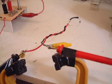
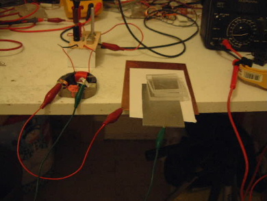
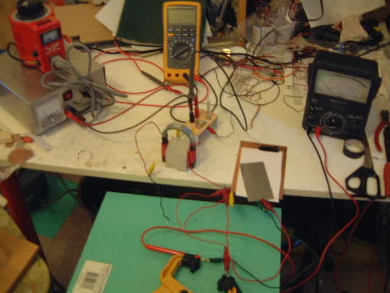
Dec 20, 2007 - Meter magnet with partial oscillator electrical contact giving better results.
Through playing around I found that I got more inductance by electrically
connecting from the oscillator to the meter magnet by placing the magnet
on the DC connection and leaving the ground connection separated, as in
the photo below.
So I connected the diode in series with the voltmeter probes and measured
this way across the plates that were in contact with the magnet's poles.
I also connected an ammeter in series too. The following photo shows this.
The result was
1 volt at 10microamps DC. Nothing to write home about, but the
best up to this point.
I then put the plate capacitor I'd made for the December 16 tests such that
voltage would be accumulated on it and measured across it.
The best I got was with a control voltage of around 4.0V giving around
1.2V on the meter.
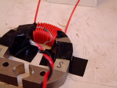
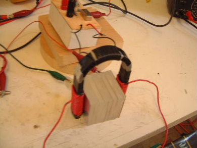
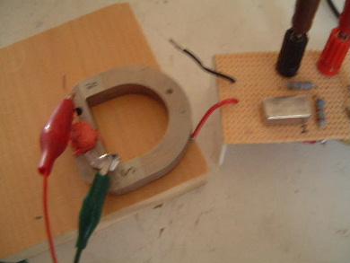
Dec 21, 2007 - Pulsing the horseshoe magnet from the plates between the legs.
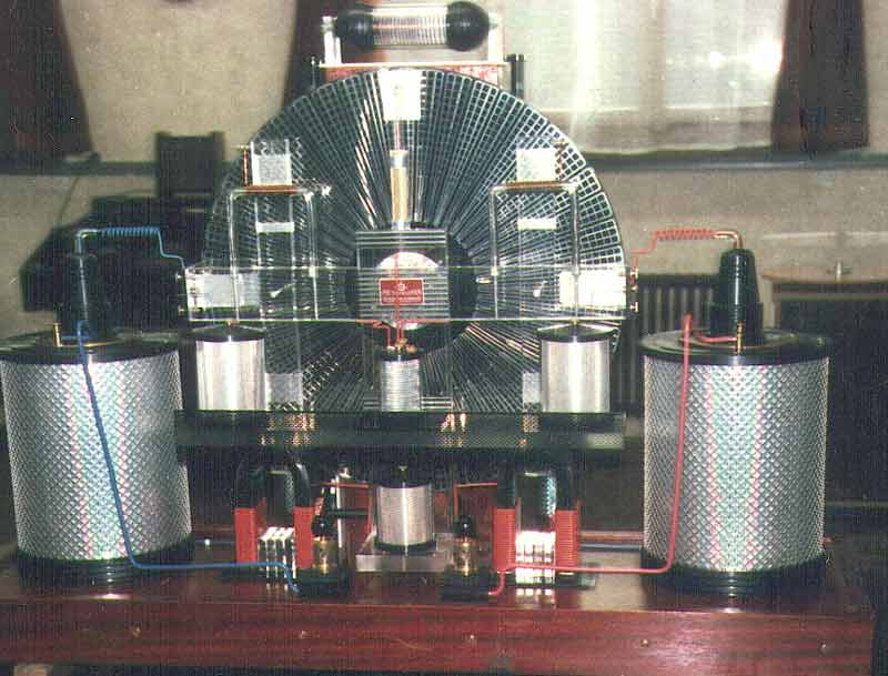
It always puzzled me why the dual disk
small machine had nothing between its horseshoe magnet legs but had
coils with around 8 to 10 windings wrapped around the tops of the horseshoes
whereas the 3kW machine's horseshoe magnets
had no coils wrapped around the top but did have something between the legs.
It was obvious that the dual disk small machine's magnets were being pulsed
Linden-experiment-style with a coil but there was no obvious way that the
3kW machine's magnets were being pulsed. From previous experiments I knew
that flat plates act as good EM antennas around these types of machines,
so I realized that maybe the plates between the legs were acting as antennas
and as a result, pulsing the magnets. So... as the following photo shows,
I hooked up the oscillator to the plates
sandwiched between the legs of the 4" horseshoe magnet.
The remainder of the test circuit consisted of measuring the voltage
coming out of the coils wrapped around the legs with a diode in series.
Charge was accumulated on the plate capacitor. I tried with the bottom
ends of the coils in electrical contact with the magnet and without.
Current was at the very
lowest measurable, 1 microamp. No voltage was measured when the
bottom ends of the coil were not in electrical contact with the
magnets. Results were found with different control voltages
when the bottom ends of the coils were in electrical contact with
the magnets:
| Control voltage |
Approx. frequency |
Coil voltage |
| 0.059VDC |
200MHz |
120mVDC |
| 6.0VDC |
315MHz |
100mVDC |
| 9.5 to 10VDC |
370MHz |
80mVDC |
All other control voltages between the above ones gave 0 coil voltage, so
some form of resonance was happening. Note that the best was at the
lowest control voltage I could give, meaning that possibly lower
frequencies could be found that would be even better. I put the digital
multimeter in place of the analog one and measured 153mV. Voltage across just
the diode was 73mV.
Without the diode there was no DC voltage and no DC current.

