
The Principle experiment was performed by Paul Baumann during a demonstration with over 30 engineers. Here is the relevant text extracted from a translation by Stefan Hartmann and Hans Holzherr on August 4, 1999.
|
As Adolf Schneider already mentioned, my colleague Bernhard XXX and I want
to try to copy the principle experiment shown by Baumann - without much hope
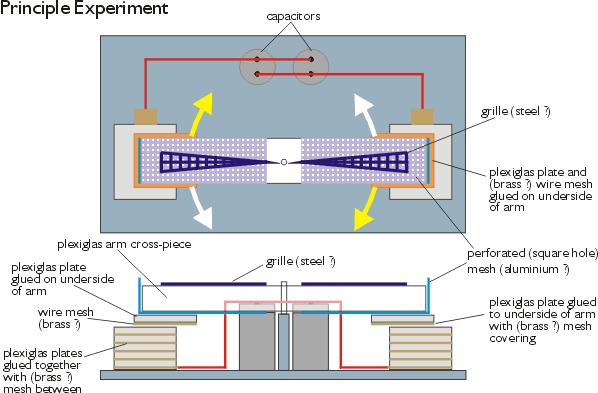
to find anything extraordinary, though. The device consists of a horizontal
swiveling plexiglass arm with a small rectangular plexiglass plate at both
ends glued to the lower side of the arm. The lower side of the arm is
covered with perforated aluminum sheets (square holes), while the bottom of
the plates is covered with brass wire mesh. Beneath each plate five additional
plates are glued onto the base plate. There is also wire mesh between each
pair of plates in the two blocks. From the mesh layer between the lowest plate
and the base a wire goes to the two capacitors, which are connected in parallel .
Baumann SEIZED the arm with both hands and turned it about ten times back and
forth (a full rotation was not possible, because the capacitors were in the way),
then measured the DC voltage with a digital measuring instrument: 60 Volts.
Then, as he short-circuited the condensers a loud crack could be heard. I don't
know if that already is an abnormal result... On my question Baumann replied that
with metal foil (instead of wire mesh) the device would not produce that effect.
Picture copyright 1999 by Hans Holzherr.
|
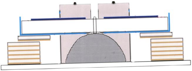
Further information - The flattened hemisphere/bell base
What is not generally known and was left out of the above diagram as unimportant was that the base for the arm was a "flattened hemisphere that seemed to be half of an electric bell". The following is from some additional private correspondance. The lines beginning with ">" are questions being asked of the visitor.
|
> You described capacitors
|
The references above to another arm machine seem to be refering to the panning arm machine or Ruck-Zuck (back and forth) machine.
|
|
A little theorizing...
The following are my ideas. If you want to stick to observations only then stick to the above reports.
|
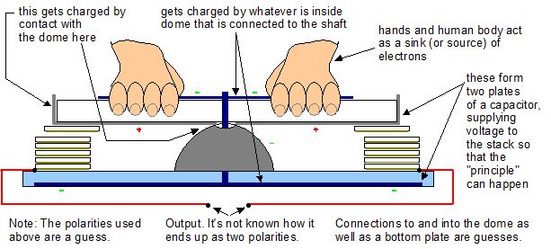
I was puzzled by why the above reports show perforated metal on the top of the horizontal arm. I realized that they might have been for electrical contact with the hand of whoever "SIEZED" the arm in order to turn it. The above diagram shows the resulting train of thought.
For a long time it was speculated that the source of the high voltage (if needed) for the principle experiment may have been Paul Baumann himself, as it's commonly known that a person can easily build up a charge of 10,000V by walking across a carpet. However, the above new information that a bell shaped base was involved brings up the possibilty that the bell may have acted as a means of charge separation thereby producing a high voltage when the arm was rotated. Here are some speculations on what may be going on inside the dome to produce that voltage. The principle being demonstrated is probably the "magic" that happens inside the stack and it is that which produced the strong charging of the capacitors. The voltage producing techniques below are just for providing an energy-conserving voltage so that the principle can take place.
Voltage using the triboelectric effect
|
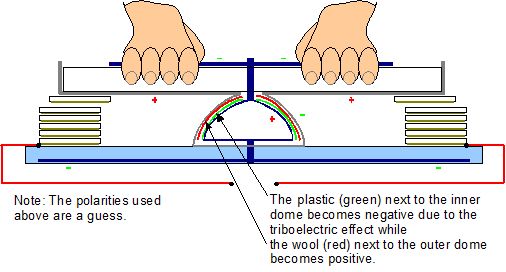
The dome might contain an inner dome and some triboelectric materials that needed to be rubbed together to produce a charge to create some voltage. This could be as simple as an inner metal dome covered in plastic surrounded by wool packed in tight. The shaft would be a metal rod connected to the inner metal dome. Since the plastic becomes negatively charged, the inner dome adjacent to the plastic would become positively charged, sending electrons up the shaft and to the hands of the person. Meanwhile, as the wool becomes positively charged, the outer metal dome would become negatively charged. It would therefore be attracting electrons from the perforated sheets that are attached to the underside of the arm.
Voltage using a Van de Graaff like effect (Faraday bucket)
The same principle used by the top dome of a Van de Graaff generator to collect charge from its belt may be involved. The shaft for the arm could have been metalic and played the part of an electrical conductor. Where the shaft went through the bell it may have been electrically insulated from the bell. The bottom of the shaft, within the bell, could have had a sharp pointed comb electrically attached to it. The points of the comb would have been near, but not touching, the inner surface of the bell. As the shaft and attached arm were rotated, the comb would also rotate and deposit charge on the bell using the Faraday bucket effect, the same effect used by the top dome of a Van de Graaf generator. The result would have been a charge separation between the bell and the grids on the arm, and hence, high voltage.
Stack and pot correspondance
Also, note that the stack of plates glued to the base, as described above, have a direct correspondance to the tall cans in the panning arm machine. In place of a bell for doing charge separation, the panning arm machine may have gotten its high voltage from the horseshoe magnet, as the Linden experiment leads us to believe the purpose of the magnets to be. A natural evolution would then be to replace the arm with a disk or disks, and voila, we have the testatika machines - disk(s), two large cans (or pots, as Baumann refered to them) and horseshoe magnets. If the magnets tap into some energy source then we can see how the panning arm machine could have been the first self running machine of the Methernithans.
Replication attempts
See here for details of an unsuccessful attempt to replicate this experiment. The original page is in German, so if the above translated version doesn't work, try the original German. You could also try going to altavista's translation website and paste in the address http://www.hcrs.at/TESTA.HTM.
