
Warning: All test measurements were done incorrectly due to lack of experience using an oscilloscope with a floating voltage source (i.e. where neither electrode is grounded) - one electrode was always being grounded. As a result this information is useful for seeing how the device was constructed and the measurements are useful for historical reference only.
Two sets of tests are shown below for April 26:
- Comparing voltage between middle front-side grid and back grids with voltage between lower front-side grid and back grids
- Looking for difference that new grid makes
For a clear picture of what grids are where, see the contruction page and look at the pictures up to April 25.
Note that for all tests there was also a 200mV AC signal from the household powerlines present. This affects what you see in the scope shots below. Note also that the disk was rotated at approximately 2400 RPM for all tests. This means that the disk was rotating at 40Hz and that the grids would see the wires at 800Hz (there are 20 wires).
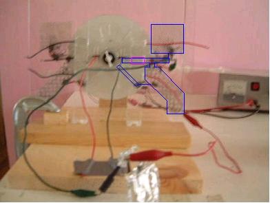
1. Comparing voltage between middle front-side grid and back grids with voltage between lower front-side grid and back grids
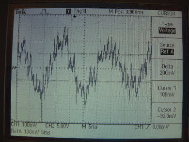
Measuring voltage between middle front-side grid and back grids...
|
|
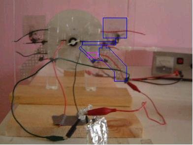
... measuring voltage between lower front-side grid and back grids.
|
|
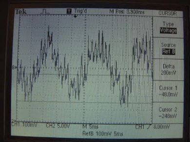
Notice that in the above two, there isn't much difference.
2. Looking for difference that new grid makes
I wanted to see what the difference the new diagonal grid made to the whole back grid combination (outlined in blue in the above pictures) but could see no noticable difference. My only guess for this is that the horizontal grid is connected to the large holed grid with an overlapping flat piece of metal whereas the diagonal grid is connected with a wire. As this is the case with the actual testatika machine, my first inclination is not to mess with it.
