
Warning: All test measurements were done incorrectly due to lack of experience using an oscilloscope with a floating voltage source (i.e. where neither electrode is grounded) - one electrode was always being grounded. As a result this information is useful for seeing how the device was constructed and the measurements are useful for historical reference only.
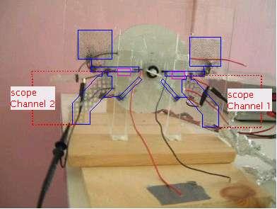
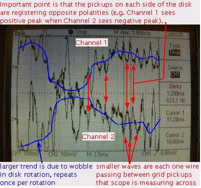
I wanted to see if the voltage at the output grids was the same polarity at all times on both sides. If so, then they are independent. If not, then they may be interacting somehow across the disk. To get simultaneous readings from both sides I simply used one channel of my oscilloscope for each side. The results are that they are opposite polarity as the oscilloscope output below clearly shows. Surprise (it was for me)!
For a clear picture of what grids are where, see the contruction page and look at the pictures up to April 25.
Note that for all tests there was also a 200mV AC signal from the household powerlines present. This affects what you see in the scope shots below. Note also that the disk was rotated at approximately 2400 RPM for all tests. This means that the disk was rotating at 40Hz and that the grids would see the wires at 800Hz (there are 20 wires).
|
|
Though puzzling, this was a bit of a relief as I was wondering how the two "pots" (the two cylinders at bottom left and right in the testatika machines) could output opposite polarities if their inputs were the same polarity. If I've replicated it correctly, then we can see that the inputs are actually opposite polarities.
