The Device
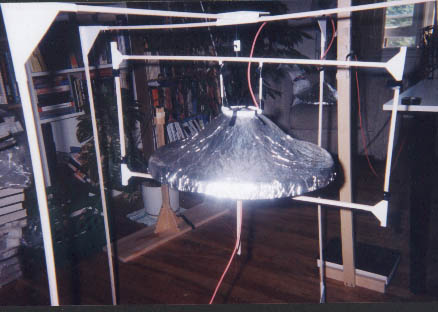
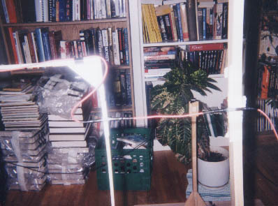
Picture 1. Close up, top view
 |
|
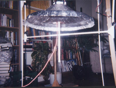
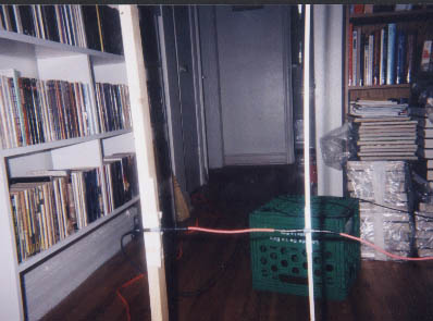
Picture 2. Close up, bottom view
 |
|
The device basically consists of two parts. The first part
is an aluminum foil dome and the second part is a copper disk.
Other parts were tried besides a copper disk and even a
different dome was at one time tried. I'll describe the
variations in the sections detailing specific experiments.
The dome looks as if you had taken a large salad bowl, turned
upside down, with a smaller bowl, also upside down, sitting on
top of the large bowl. The opening of the large bowl is 15 inches
in diameter as per the T. T. Brown device.
The copper disk is simply a thin plate of copper cut into a disk
3 inches in diameter.
The copper disk sits just inside the rim of the upside down
dome (see Picture 2). The dome and disk are fixed
relative to each other with only air as a dialectric between
them. This was done by creating a balsa wood and plastic
frame surronding the device. The dome is suspended from the
top of the frame using plastic rods (see Picture 1)
and the copper disk is sitting on top of a balsa wood stick
that is attached to the bottom of the frame (see Picture 2).
Note that even though the dome and disk are fixed relative
to each other, the distance between them is adjustable.
The Test Stand
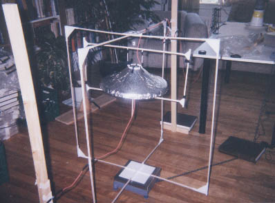
Picture 3a. Device suspended from test stand
 |
|
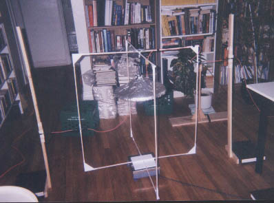
Picture 3b. Device suspended from test stand
 |
|
The frame is then suspended from a test stand using a thin
sewing thread. Pictures 1 and 3a show that this is so even
though the thread is invisible (same color as the background).
The test stand is made of balsa wood and plastic. It in turn
sits on a digital scale (see Pictures 3a and 3b). The digital
scale sits on the floor. The white rectangular piece of
plastic at the bottom center of Pictures 3a and 3b is the
part of the test stand that sits on the scale and the silver
and blue object below the white rectangle is the scale.
The idea is that if the device gets either heavier or lighter,
the amount that it gets heavier or lighter by will show on the scale
as a change in weight of the whole test stand.
The Wiring
Picture 4a. Test stand to external wiring
 |
|
Picture 4b. Test stand to external wiring
 |
|
The wires used are the type used on typical multimeters. The
purpose in using this type of wire was to provide good
insulation since high voltages are being used.
Picture 1 shows the wire for one polarity descending from the
top of the test stand to the aluminum foil dome. Picture 2
shows the other polarity ascending from one side of the
test stand to the copper disk.
Pictures 4a and 4b show the connections that extend from the
test stand to the two posts that sit on the floor to either
side of the test stand. These posts are best seen in
Picture 3b. Keep in mind that the test stand must
be as free as possible to get lighter or heavier with as little
external influence as possible. For this reason the weight
and stiffness of the connections shown in Pictures 4a and 4b
have to be as little as possible.
The Power Supply
The power supply is a high voltage power supply capable
of between 50KV and 150KV DC. It basically consists of
a control unit connected via umbilical to a second unit
that contains a voltage multiplier board immersed in
mineral oil. The bottom portion of the multiplier part
can be seen in the top right corner of Picture 3a.
Unfortunately I have no way to measure actual voltage
as it ends up on the experimental device. The only
criteria I have for voltage is the published range for
the power supply (50KV to 150KV DC) and the fact that
voltage is adjusted by a potentiometer on the control
unit that ranges from 0 to 100.
The Digital Scale
The digital scale is a DI-8K purchased from Denver
Instrument. It is capable of measuring up to 8000 grams
with an error of +/- 0.1 grams.

