October 25, 2003 - First test failed, arcing at 8kV
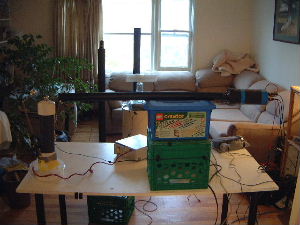
The test setup
View of everything. The
power supply is on the left
side of the table. The long horizontal black rod is the
HV probe.
 |
|
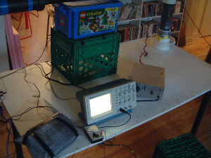
From left to right on the table is the control unit for
the digital scale, ammeter, oscilloscope
and the control unit for the power supply. Note that the control unit for the
digital scale is completely enclosed in fine wire mesh (window fly screen)
which is grounded.
 |
|
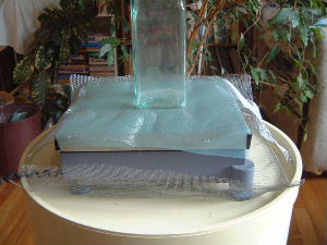
The pan for the digital scale has a polyethylene cover
on it followed by a grounded fine wire mesh. The scale is also sitting on
another grounded fine wire mesh. Note that the two meshes are not in
physical contact.
 |
|
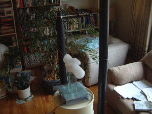
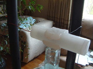
The thruster sitting on a glass tower which is sitting
on the scale.
 |
|
A view showing the wires sticking out horizontally so
as to minimize any lift effect that the wires might produce. Note that
two tests were done, one with the thruster as shown and the other with the
thruster flipped 180 degrees such that the side that is "up" in the picture
below was "down" instead.
 |
|
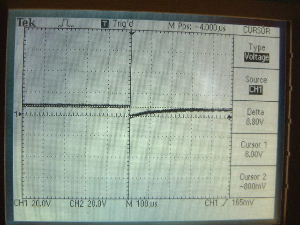
The test - failed due to arcing inside the thruster
As the scope reading clearly shows below, there was arcing inside the
thruster meaning that there is one or more air cavities either inside
the thruster tube or at one end. A sanity check was done by replacing
the thruster with a gravitator.
The gravitator permitted voltage to increase to as much as 50kV with no
arcing showing on the scope.
At all voltages, a weight gain was showing on the scale. This was
true regardless of which side of the thruster was "up". The scale
did show an unbalanced condition as long as the weight gain was showing.
The weight gain increased as the voltage increased.
No matter how high the voltage was turned up (though
it was never turned up very high) the scope showed that the voltage at
the probe did not exceed 8kV until it arced. This is the spike on the
scope picture below. Voltage then built up again as shown to the right
of center. Note that as voltage was turned up, the 8kV maximum still held
but the spike was larger.
 |
|
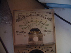
At lowest power supply setting the ammeter read
around 30-40 microamps. Note that the current was probably present
mostly during the arc as the meter was making a rapid fire clicking sound.
The needle appeared steady probably because the internal mechanism did not
have time to move before an arc occured again. Note that as voltage was
turned up, the amp reading also increased.
 |
|
At Zoltan's suggestion I did some tests to eliminate the weight gain
that was showing up on the scale by improving the sheilding on the scale.
The following elimination tests were done:
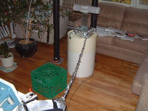
- The scale unit that the thruster sits on was completely wrapped in
aluminum foil as shown in the pictures below. First this was tested
without shielding the cable too. The weight gain was the same.
- A simple idea came to mind. I removed the glass jar that the thruster
was sitting on and instead put a milk crate upside down on top of the
round table that the scale unit is sitting on. Note that the milk
crate was NOT sitting on the scale. I then put the thruster on top
of the crate. The weight gain was the same even though there
was no way for the thruster to affect the weight on the scale.
- I removed the milk crate and put the glass jar back on the scale. I
then replaced the thruster with the gravitator (which does not arc).
There was no weight gain. The scale remained at 0.0 grams.
This is a very good sign as it indicates that when we do get the
thruster to not arc, it will likely have no affect on the scale.
- I put away the gravitator and put the thruster back in place. I then
shielded the cable so that now the entire digital scale -- the control
unit on the table, the cable, and the scale unit that the thruster sits
on -- was all grounded. There was no weight gain. The scale
remainged at 0.0 grams
- To prove that step 4 above was not caused by the fact that the
scale was completely wrapped in aluminum foil and that the foil was
somehow physically preventing a weight change from showing, I put a
single playing card on the thruster. The scale immediately showed a
weight gain of 1.3 grams.
The completely sheilded digital scale after step 4
above.
 |
|
A closer view of the scale unit completely wrapped in
aluminum foil.
 |
|
Putting the single playing card on the thruster showed
a weight gain of 1.3 grams. See step 5 above.
 |
|
The conclusion is that the weight gain showing up on the scale's control unit's
LCD panel was due to the arcing in the thruster affecting the electronics in
the digital scale and not due to any actual weight gain in the thruster.
Step 3 above gives hope that not a lot of grounded sheilding will be needed
on the scale once we do get the thruster to not arc.
However, a force should
have been measured despite the arcing at 8kV. This indicates that this
device will not produce thrust.
I dug cut off the ends of the wax and then dug out the interior of the
thruster. After a few hours of digging I found an easier way of removing
the wax from inside the thruster by heating two metal skewers (long metal
sticks) and pushing them into the wax, thereby melting it out.
Wax had gotten into one of the plaster endcaps and broken it so I replaced
it with a balsa wood one instead (see picture below).
I then put an endcap of wax on one end and gradually filled the interior
of the thruster (see picture below). After letting each pouring harden,
I tested it to see if it arced inside the new wax. Instead of arcing inside
the wax, it would arc in a section not yet filled with wax. I would then add
a little more wax and repeat the testing. After filling it about 75% of the
way, the wax started arcing internally. So I removed a bit of wax and tested
again. I continued doing this and it kept arcing internally until I'd dug it
all out again! At that point, I ran out of time.
My guess is that during the initial repouring I had the thruster interior
very well cleaned out so it arced easily in some places where there was no
wax instead of arcing in any cavities in the parts that I had already poured
wax. During the gradual pouring, the interior walls of the thruster were
gradually getting coated with wax until finally the areas that were not
completely filled with wax would no longer arc and instead arcing deeper
down would start to occur.
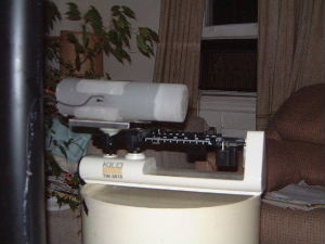
I did a test with a triple beam balance to see if there was any weight
change (see picture below). Note that it arced during this test as before.
There was no weight change. And yet if I gently put a
single playing card on the thruster while it was on the balance, the balance
easily showed a weight increase.
The new wooden endcap.
 |
|
Gradually pouring wax.
 |
|
The triple beam balance test.
 |
|

