The Idea and Work Done so far
The basic idea behind Steve Thompson's approach to the 45 gallon
drum experiment was to use a motor at the top of the drum in order
to produce the motion instead of an opposing top magnet. This
page details my attempts to make build using this design.
Note that this attempt used my
Mark 1 version and was abandoned due to technical difficulties
as detailed in the conclusion below. I later came up with
a better
approach using a motor, detailed here.
Thus far I have the motor assembly, but the motor is making the
top cone spin as well as wobble whereas really I am just after
wobbling. The motor driven arm should rotate around in the
drum, putting outward pressure on the top cone, thus making
it wobble. The motor should rotate independent of the cone
such that the cone does not spin.
At the highest speed that I am willing to run it at, I get
about 1 rotation per second. I could probably get double
that.
The only interesting result that I have gotten so far was
when doing a run with the large wheel. I had the cone
rotating at just under 1 rotation per second and had been
running the motor for less than 30 seconds. The wheel had actually
roled off of its track and contact between the cone and the
arm was made directly from the wooden outer edge of the arm and the
rim of the cone. I heard a very quiet humming sound like you
would hear if you were running a wet finger on the rim of a wine
glass. This sound lasted only about 15 seconds and then went
away, probably due to a speed change since my control for the
speed is a handheld racing car gun and the pressure of my finger
on the trigger probably fluctuates. This humming sound is obviously
caused by vibrations somewhere.
Currently I have tried two types of contacts with the cone
(see pictures below):
- Pully riding on a wire, the wire attached to the cone.
Just as the pulley puts pressure on the cone, thereby
pushing it towards the drum ring magnets, so to the
cone puts pressure on the pulley axle, thereby preventing
it from rotating. Instead the pulley remains at a fixed
location on the wire/cone, rotating the cone.
- Large wheel riding on the cone.
In this case I attempted to make a track on which a
wheel could ride. The track was made of a stack of
wires fixed to the inner rim of the cone. There were
two problems with this approach: the wheel just rode
itself off of the track and the track (made of a stack
of wires) made the cone rim too heavy such that it
dropped lower than it should have.
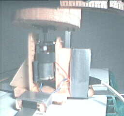
Pictures of the Motor Assembly and Arm
Upside down view of the motor assembly.
 |
|
Upside down view of the motor assembly.
Details of the gear box.
 |
|
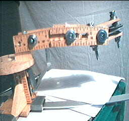
Upside down, side view of the arm that
extends from the motor out to the cone. Note that it is
adjustable in many ways. Note that at this time, the pulley
is attached to the end of the arm.
 |
|
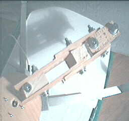
Bottom view (this is the underside) of
the arm that extends from the motor out to the cone.
 |
|
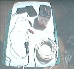
The controls. Clockwise from top:
the electric car racing gun (rheostat) for controlling
the speed of the motor, the 6 volt battery, coil of telephone
wire, the alligator clips for attaching to the battery.
 |
|
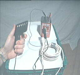
The controls. I am holding the speed
control (electric car racing gun). The alligator clips
are connected to the battery as they would be when the
motor is in use.
 |
|
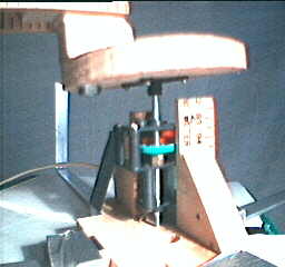
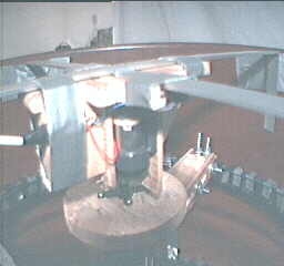
Details showing the motor assembly in
the drum. This is the rear view with the arm extending
rearward and to the right.
 |
|
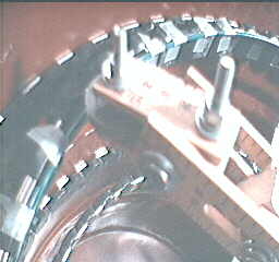
The Pulley Attempt
Top view showing the pulley making contact
with the cone. A wire (fence wire) shaped as a ring was
taped to the inside of the cone rim to act as a track for
the pulley to run on.
 |
|
Close up of the pulley making contact
with the wire track.
 |
|
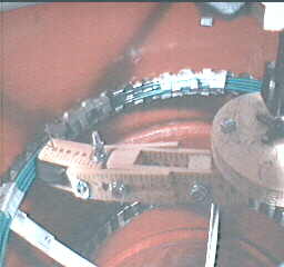
The Large Wheel Attempt
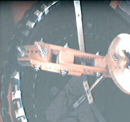
View showing the trial with a large
wheel making contact with a stack of wires taped to the
inside of the cone rim.
 |
|
Close up of the large wheel making
contact with the wire track. An extra wire was taped to the
bottom two wires to act as a sort of bottom ledge for the
wheel to ride on.
 |
|
Conclusion
I did actually carry this work a little further but did not
record anything about it since it did not work out. This
approach may in fact be viable but not with my Mark 1 version.
This is due to the large gap between cone magnets and drum
ring magnets (approx 2 to 3 inches). This large gap meant the
the motor arm had a long way to push the cone rim accross.
But, it not only had to push it accross but also downward.
But, even worse, enough downward force had to be propagated
down to the cone below as well so that it also would wobble.
My construction could not deliver that force and still have
enough power on the motor to also turn the arm.
As such, this attempt was abandoned.
