
The objective of this experiment was to replicate the experiment of T. Townsend Brown wherein two devices spin around a tower. The two devices are basically capacitors that are charged using very high voltages, starting from 15KV DC and going up. I have some of my videos of some of my devices in action at the bottom of this page.
The basic design used was one that I had seen demonstrated at the International Symposium on New Energy in 1996. The classic reference for this experiment is the US patent 2,949,550, Electrokinetic Apparatus, Aug. 16, 1960, T. T. Brown.
T.T. Brown seemed to think that there was some mysterious force involved here but from my tests I've found only ample ion propulsion/ion wind so far. I haven't done any vacuum chamber tests.
The Basic Devices
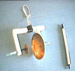
So far I have experimented with two basic devices. The first is the saucer shaped one and the second is one involving a small dome shape. The two are shown in the following pictures.
|
|
Both devices consist of two electrodes, one charged positively and the other negatively. The main difference between the two is that the saucer device always moves in the direction of the wire that is in front of the saucer whereas the dome device most often moves in the direction of the positive thereby making it a strong candidate for the Biefeld-Brown effect, but sometimes it reverses direction depending on the voltage or current. However, everything I've seen can be accounted for by some sort of ion wind or possibly dielectrophoresis.
The remainder of this page deals more with the saucer device but has some relevant details regarding the experimental setup that applies to both devices. Follow this link for more details on the dome device.
The saucer shape is really two brass plates that are held together. One of them is rightside up, the other is upside down. They are held together by the four pieces of plastic that can be seen in the above picture, spaced around the circumference. I could not solder the brass plates and didn't want to interfere with their contact by gluing them together so I used the four plastic pieces.
Held apart from the saucer is a piece of brass wire. The brass wire is bent in a curve to match the curve of the saucer. The brass wire is held apart from the saucer by two pieces of plastic, visible in the picture. This is so that the saucer and the brass wire act as a unit but have no electrical connection between them. The air between them acts as a dielectric.
As can be seen in the above picture, one wire is connected to the back of the device and the other to the brass wire. The electrical connection is made with aligator clips. During my experiments, voltages between 50 KV DC and 150 KV DC were applied, one polarity to the saucer, the other to the brass wire.
The brass wire in the picture above has black electrical tape covering its ends. This actually causes the device to behave poorly, but it was the only closeup picture I had. The black tape should not be there normally.
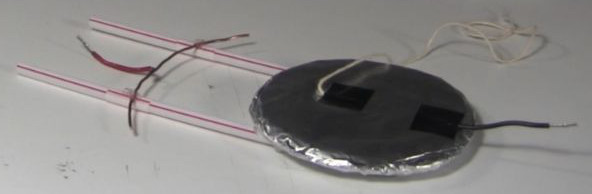
In my experience, many devices are possible, to the point where once you've succeeded with one device, it is trivial to come up with more. I've seen saucer shaped electrodes, sausage shaped electrodes, cone shaped electrodes and bowl shaped electrodes. In the photo below is one where the saucer is made of balsa wood wrapped in aluminum foil.
|
The Experimental Set Up
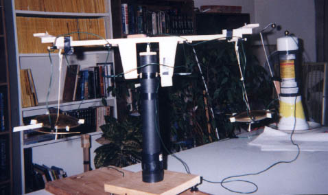
The picture below shows the devices suspended from a tower. In the picture, they are spinning as can be seen from the angle which the string makes.
|
The following diagram shows the tower set up from the front and top views. The main point of these diagrams is to show the wiring harness.
|
|
Some advice to anyone trying to build one of these:
- The rotor (the long piece of balsa wood that acts as the top of the 'T') must be able to spin as freely as possible. In this case it is balanced on the head of a ballpoint pen. The less friction, the better.
- The wires for different polarities must be kept apart as they are in the above diagrams.
- The wires that contact the chrome ring do not actually have to touch the ring. At 50KV DC the charge will arc accross. A gap of .5 mm will work fine.
- Make sure when you build it that the pen tip is perfectly centered in the PCV tube. Make sure that the robertson screw that is inside the rotor is perfectly centered. Doing this will make balancing a lot easier.
Experiments and Results from my Lab Book
I won't reproduce all the details of my lab book here but I will still give some details of my experiments. In all cases I used this high voltage power supply.
Basic saucer device tests (September 6th to October 26th, 1997)
My first attempt with this was immediately successful. However, with each slight adjustment the amount of friction would change significantly so I could not make any qualitative measurements. The fastest that I ever got it spinning with the saucer devices was about 60 complete revolutions per minute.
I did toy around with some other shapes, bowls, which I will add details about later.
Tests for ion wind (August 23rd to 29th, 1998)
I made a significant effort to eliminate ion wind as a reason for the propulsion effect. I tested by placing the saucer device in a clear plastic tube whose ends I could cover as needed (my first tests were to actually place the device in two cake containers but the fit was two tight). The following two pictures show the set up, one with the ends of the tube covered and the other with the ends uncovered.
|
|
My results were as follows:
- Both ends of the tube closed - no movement
- Saucer end of the tube closed, other end open - no movement
- Brass wire end of the tube closed, other end open - no movement
- Both ends of the tube open - movement
I also tried another type of container that had an exposed top but I had similar results.
My conclusion was that the effect is likely ion wind.
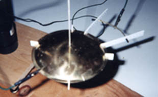
Saucer device in mineral oil (August 30th to September 1st, 1998)
I also did some testing with the saucer device immersed in mineral oil. See the following pictures.
|
|
|
The more complicated rigging on the rotor in the pictures above was necessary to keep the saucer device from floating on the mineral oil. This saucer was actaully carved out of balsa wood and covered with aluminum foil. Mineral oil is very messy and I didn't want to get my brass saucers full of it.
Mineral oil is what is used in my power supply to prevent discharging between the capacitors and diodes. So I figured that if I immersed the saucer device in mineral oil and it still moved, then I've eliminated ion wind.
It did move, although very slowly. It had only a short arc within which to move. If you call the start of the movement, 1, the middle of that arc, 2, and the part of the arc near the other end of the container, 3, then my results were as follows:
- An initial low voltage starts it moving but once it is a little away from the starting position, the voltage must be turned up to keep it moving.
- If started in the middle of the tank then higher the voltage is needed to get movement.
- Low voltage is needed for movement.
Since it only had a short distance to go, this slow movement was normal. Whenever, the device is in air (instead of mineral oil), it starts up slowly and picks up speed as it overcomes friction. I wish I had a large enough vacuum chamber.
During one test run there were some bubbles sitting on top of the mineral oil above the saucer. When the saucer moved, these bubbles moved in the opposite direction, indicating that the effect was propelling the mineral oil.
In this case, due to the reverse movement of the oil that opens up the possibility of dielectrophoresis being the cause. In dielectrophoresis an asymetric electric field can cause neutral molecules to move from the less dense area of electric field to the denser, using the molecules as a propellant much as air is used by a jet engine to propel it forward. However, I would have guessed that the denser field would be at the wire and therefore the direction would have been the other way, but I could be wrong. It's also possible that ionization is still occuring here at the surface, and hence the moving bubbles.
Conclusions
The saucer device detailed above always moved in the same direction, regardless of the polarity. The fastest that I ever got two of them spinning around the tower was 60 complete revolutions per minute. The higher the voltage, the faster they moved.
As to what is the means of propulsion, my results indicate it being due to air (ion wind) or mineral oil (dielectrophoresis) as a propellant, however there are still questions regarding the mineral oil test.
That is not to say, however, that all devices utilize the same propulsion techniques. Some are probably just ion wind, others could be making use of other techniques such as dielectrophoresis, and others could be making use of combinations. If your feed wires are sufficiently thin and poorly insulated then they will also ionize the surrounding air, producing propulsive effects. Given the difference in ion mobility between positive and negative ions in the air, two such opposite polarity feed wires interacting ionically with each other would result in movement in the direction of the positive wire. I've had 18 AWG wire with around 1mm thick rubber insulation leak through the insulation at points along its length when it was sufficiently near an oppositely polarized object. Propulsive ionization can also occur through wire connection points. Black electrical tape is insufficient to insulate against this. See my Poynting flow thruster experiments where I methodically eliminate sources such as these.
That is about all I can say. I cannot make any significant qualitative measurements because with the above design, the amount of friction varies widely each time an adjustment is made. However, when spinning at top speed, it is a very impressive sight.
Fun ion propulsion
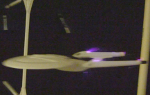
|
Just for fun I purchased a small Star Trek Enterprise model from a local hobby store and added ion propulsion to it. |
Videos
Make Ionocraft/Ion Wind Spinning Disks
I made the following video to show the impressive sight of the saucers being propelled with ion wind and to show others step-by-step how to do it.
Star Trek Enterprise Model with Ion Propulsion added
This is a fun video where I used the ion wind principle to propel a small store-bought model of the Star Trek Enterprise.
