Hoping that the theorized force for the
Poynting Flow Thruster
described by Jean-Louis Naudin was real I set out to repeat the
experiments. I had first done tests in May 2001 but the results were
inconclusive due to issues with my old rotor. These new tests were
waiting for me to build my
new rotor.
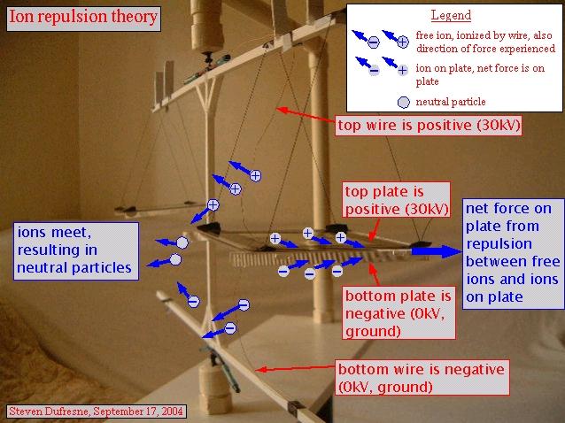
Unfortunately the source of the movement turned out to be just another form of
wind. The following diagram illustrates my theory as to what is going on
and the details that follow it show how my experiments support the theory.
Note that I am not a theorist so while the experimental results prove the
force is from some form of wind, the theory may need work (feel free to email
me with refinements).
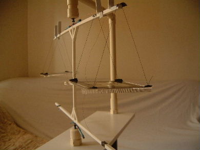
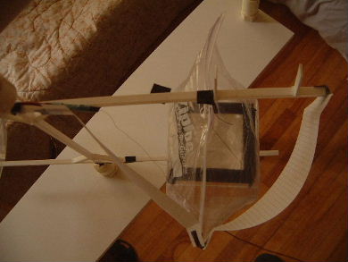
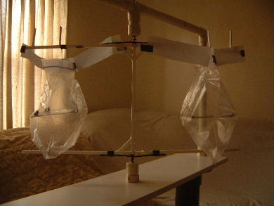
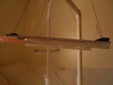
Each thruster was made from the top part of a CD case. The plates
are thin aluminum foil squares (9mmx9mm) with rounded edges. The
edges of the plates were covered with strips of black electrical tape
for insulation. The bare copper wire used was 0.009" in diameter.
The insulated wire used was multimeter wire.
Experiments (Sept. 14-17, 2004)
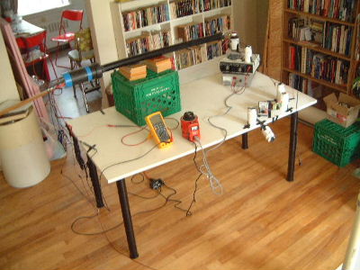
The following is the power supply and measuring instruments setup used
for the experiments.
Clockwise from top left:
HV probe,
30kV power supply,
ammeter (and accompanying plastic pill bottles for keeping the wires
suspended), variac for the 30kV power supply, Fluke digital multimeter.
 |
|
Note that in these experiments I was able to push the 30kV power supply
as high as 39kV.
Experiment 1 - Bare wires connected to back of thruster plates
I electrically connected to the thrusters using bare copper wires.
They were taped with aluminum tape to near the rear of each plate.
Things were very quiet except for slight clicking/hissing at the power
supply.
At 24kV and approximately 25uA it started moving in the direction
predicted by the Poynting flow thruster theory (in the
direction opposite from the side that the wires were attached) as
the animated GIF and QuickTime movies below demonstrate.
At 30kV and 50uA it was moving quickly at
around 20 RPM.
|
|
Animated GIF (586K) derived from frames from
QuickTime movie
 |
|
For a QuickTime movie of the above click
here (2Meg).
If you don't have QuickTime you can download it
here.
Note that if you hear a repeating clicking sound in the recording
this is an artifact introduced by the camera due to its proximity
to the HV thrusters.
Experiment 2 - Insulated wires connected to back of thruster plates
I replaced the bare copper wires with insulated wire (multimeter
wire). They were connected using aluminum tape to near the rear of each plate.
Note that I did have some leakage as the current at 30kV
was 40uA. This 40uA is close to the current pulled using bare wires above.
A quiet hissing was heard from the area of the thrusters and was likely
from ionization occuring where the aluminum tape imperfectly covered
all of the multimeter wire touching the plate (difficult to do due to the
thickness of the wire).
At 30kV and 40uA there was no movement. Given that
leakage is supposed to help sustain thrust resulting from the Poynting
flow this was an indication that a force should have been produced even
though insulated wire was being used.
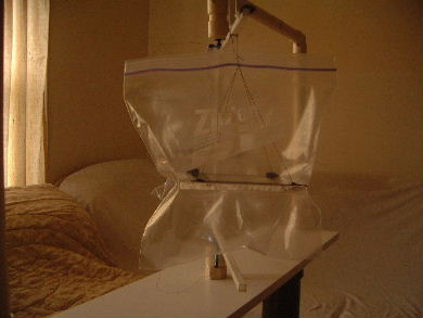
Experiment 3 - Plastic bag test, bare wire left alone
Trying to duplicate Jean-Louis's approach, I put each thruster
in a plastic bag to help prevent any ionization on the wire from
causing thrust. I made sure the bare wire emerged from the
bag at the top and bottom of the bag.
At 34kV and 150uA it moved slowly in the
direction predicted by the Poynting flow thruster theory (in the
direction opposite from the side that the wires were attached) as
the animated GIF and QuickTime movies below demonstrate. There was
a lot of hissing in the area of the thrusters.
|
|
Animated GIF (540K) derived from frames from QuickTime movie
 |
|
For a QuickTime movie of the above click
here (3.6Meg).
If you don't have QuickTime you can download it
here.
Note that if you hear a repeating clicking sound in the recording
this is an artifact introduced by the camera due to its proximity
to the HV thrusters.
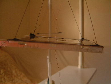
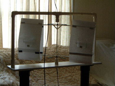
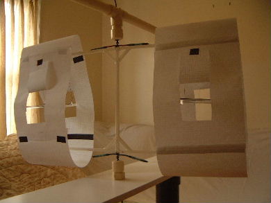
Experiment 4 - Plastic bag test, top bare wires with paper wind deflectors
I still suspected that the lengths of the bare wires that were exposed could
still produce a undirectional thrust and that that thrust would result from
the above explained theory. I attached strips of paper near but not touching
the top wire in a location that would negate any wind
produced according the the above theory. Note that two strips were
needed, one to block backward flowing ions from the wire and one
adjacent to it to block sideways flowing ions.
The thrusters moved but slower AND IN THE WRONG DIRECTION
as the animated GIF and QuickTime movies below demonstrate. The reason it
moved in the wrong direction is likely that the ions from the wire hit the
paper shield, became neutral, and bounced off imparting their momentum
to the paper shield. The paper shield thus became a sail.
Top view showing paper strips to shield backward
and sideways flowing ions.
 |
|
Horizontal view.
 |
|
Animated GIF (454K) derived from frames from QuickTime movie
 |
|
For a QuickTime movie of the above click
here (5Meg).
If you don't have QuickTime you can download it
here.
Note that if you hear a repeating clicking sound in the recording
this is an artifact introduced by the camera due to its proximity
to the HV thrusters.
Experiment 5 - Plastic bag test, top bare wires with paper wind deflectors,
bottom wires rearranged for minimal effect
Guessing that the bottom wire was making the remainder of the contribution
of flowing ions, I adjusted the wire connector so that the wire was
no longer drooping downward and I also changed the curve of the wire so
that where it was near the bottom of the bag it was oriented in line
with the direction of movement.
Turning the power supply all the way up to 38kV and 250uA I could
occasionally get it to move in the wrong direction
but never managed to capture it on a short enough clip to post it. Most
of the time there was no movement.
This means that the Poynting flow thruster theory is
not the cause of the original movement (and that plastic bag tests are
not valid unless careful consideration is given to the feed wires).
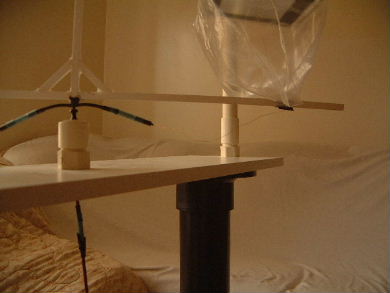
Before adjusting bottom wires.
 |
|
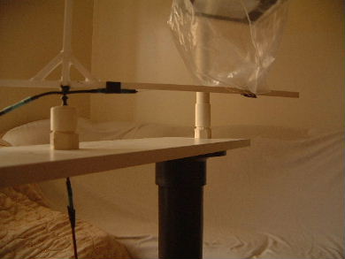
After adjusting bottom wires.
 |
|
Other Experiments
The above experiments result in a clear demonstration that the effect
is not that described by the Poynting flow thruster theory. During
the course of exploration I actually did some other experiments that
also support the conclusions. They are superfluous but fun to look at.
Due to space requirements I'm putting still photos only (though AVIs
are available for the asking).
The top wire was left near the back but the
bottom wire was moved to the center. I'm not sure what the result
should be according to the Poynting flow thruster theory but according
to the above theory it should be less than if both wires were near the
back. This turned out to be the case.
 |
|
Both wires are connected at the center but are tilted
sharply backward. According to the Poynting flow thruster theory
this should result in no movement but according to the above theory
it should give a strong movement. It gave a strong movement, perhaps
stronger than when the wires are connected at the back.
 |
|
Both wires are connected at the center and are
directed straight up. According to both theories this should result
in no movement. It did not move.
 |
|
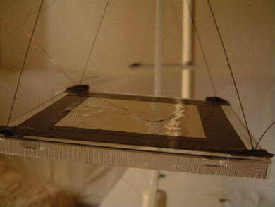
The wires were connected near the back but a
plastic sheet was placed to cover the entire back, blocking most
wind that would be produced. Not only did it block the wind but
redirected it forward. This one moved in the direction of the
plastic sheets!
 |
|
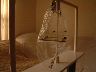
The wires were connected near the back but
a sheet of paper was placed to cover back, front, top and bottom.
Note that the only bare wire not enclosed at least in part by the
paper was that stretching to the rotor connector along the rotor
arms at the top and bottom. There was no movement.
 |
|
Flaps were cut in the paper so that there could
be a hole at the front to admit air and at the back to let the
ionized air out. This one moved slowly.
 |
|