Low Friction PVC Stator/Rotor
This stator/rotor design is based on one I originally saw used by Transdimensional Technologies, Inc with their lifters. The rotational movement is very low friction and the electrical wires coming from the power supply arrive at the center of the rotor from directly above and below.
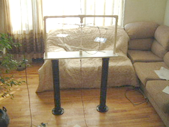
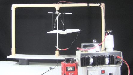
In the photon on the left below one of the the wires coming from the power supply is coming from the ceiling and the other from the floor (ground wire). This reduces the chance that movements of the devices will be derived from attraction to or from these wires. The tall black legs are ABS and cause the rotor to be relatively centered between floor and ceiling.
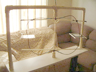
The actual rotor is interchangable. The one in the photos below is a lightweight rotor made of hollow plastic bars hot glued together.
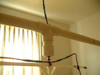
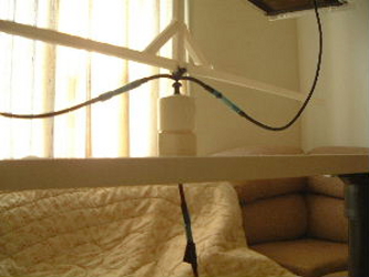
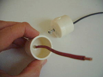
Below are close-ups of where the stator meets the rotor. The tops and bottoms of the rotor each have a small screw hot glued to them with the tip pointing up (and down) in these pictures. The screw's threads have been filed off. After soldering the two connecting wires to it, it was then painted with a thick layer of liquid black electrical tape. The stator has a robertson screw screwed into from the bottom (and top) such that you can see the head of the screw clearly. Any exposed threads have been filed off and as much exposed area as possible has been painted with liquid black electrical tape. The tip of the screw from the rotor is sitting inside the head of the screw head from the stator.
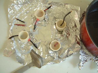
Below are the parts of the stator under construction (the parts with the screw heads mentioned above). In the 2nd photo you can see that paraffin wax was poured into the various parts for further insulation. Ignore the two caps and two wires directly above the ladle. They were not used in the end.
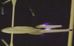
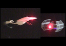
Below is a shorter version where I'm not so concerned about what forces are involved, just as long as it works. In this case I've modified a plastic Star Trek Enterprise model to do ion propulsion. Not the ground wire running across the table in the middle of the photo. The positive high voltage wire is coming from the high voltage power supply on the right and going up across the top right side of the stator.
Example of where I've used this test rig
Video - Make Ionocraft/Ion Wind Spinning Disks
I made the following video to show the impressive sight of the saucers being propelled with ion wind and to show others step-by-step how to do it.
