|
|
|
The semi-charge model of the dipole-molecules in
dielectrics
a new scientific discovery based on the
measurement results of E-field thrusters
Our research of the E-field thrusters was not based on a blind belief in some mysterious forces described by T.T. Brown, but on quantitative predictions that were derived using the officially accepted formulas and methods of electrostatics. Since Brown did not explain the source of the detected reactionless thrust in his E-field thrusters, our main aim was to find the possible source and mechanism of such uncompensated forces, not only qualitatively but also quantitatively.
Preliminary theoretical research
One possible source of reactionless thrust was predicted by the calculations of dielectrophoretic CFE forces in solid and liquid dielectrics. The qualitative description of the dielectrophoretic CFE forces on the dipole molecules is described on the page dieltutor.htm (fig. 5a), and there is no doubt that a resultant electrostatic force will push the polarized molecule (and thus the neutral body of the dielectric) towards the greater E-field intensity. These dielectrophoretic forces acting on the dielectric usually oppose the EP (electrostatic pressure) forces on the electrodes (analyzed on the page ethrform.htm), and the qualitative knowledge of this phenomenon is not sufficient to make any conclusion whether the resultant of these two opposing force components could result in a substantial reactionless thrust on a practical E-field thruster or not.
Therefore the quantitative analysis of the CFE forces was unavoidable, and the first attempt to derive the formulas for a cylindrical and spherical capacitor has been described on the page fullcylsph.htm . The basic assumption in this analysis was that the polarized molecule can be modeled as an electric dipole that consists of a positive and a negative charge at a fixed distance from each other, mechanically fixed together. Logically we also assumed that when such a dipole is placed in a converging E-field the resultant dielectrophoretic force on it can be calculated as the vectorial sum of the Coulomb forces that act on the positive and the negative charges of the dipole. Naturally for calculating these Coulomb forces the well-known definition formula was used:
![]()
The meaning of the E-field intensity E in this formula is explained so that it originates from all other charges except from the test charge q. That means, when calculating the Coulomb force, one should know the E-field intensity at the point where the charge q is situated when the charge q is absent. This definition is based on the concept that the E-field component generated by the test charge q can not develop any force on the charge q (on itself) because that would violate the Newtons 3rd law. In the case of a dipole this reasoning would be also extended on the other charge of the dipole since they are mechanically fixed together. So when the electrostatic force is calculated on a dipole we have to know the E-field intensity that is developed by all other free charges and dipoles at that point in absence of the one dipole that we are examining. This reasoning and approach has been used by the official science when calculating the polarizability of dielectric molecules, and can be found in electrostatic textbooks.
Using this method to calculate the effective local E-field intensity
that should be substituted in the above formula (see: the first approach
on the page fullcylsph.htm),
the analysis predicted so big reactionless resultant thrust on the
cylindrical and spherical capacitors with two different dielectrics that
it was highly questionable whether these results could be correct.
Therefore the same analysis has been also performed taking the E to
be the minimal E-field intensity that must be present in the dielectric,
that is the macroscopic E-field intensity that can be easily calculated
with the known formulas. Using this second approach we get much smaller
uncompensated forces, but the analysis still predicts significant
reactionless thrust for the mentioned capacitors. This second analysis was
not demonstrated in details on the mentioned page since it can be easily
repeated using the same process as in the first approach just using a more
simple formula for calculating the E that determines the
electrostatic forces on the charges. Only the derived final formulas of
this second approach were given at the bottom of page fullcylsph.htm
under the heading The lowest limit of thrust.
Experimental verification
The next step was to perform measurements that could confirm or disprove the validity of the derived formulas. The expected thrust was measured with a sensitive torsion pendulum, the applied high voltage was provided by a 35kV HV PSU with continuously adjustable output voltage, measured with a HV probe and a digital multimeter.
A cylindrical coaxial capacitor-thruster was constructed with two different dielectrics filling the two halves of the space between the inner and outer electrodes. The figure below illustrates the cross-sectional view of the cylindrical thruster with two dielectrics and the expected force components on the electrodes and on the dielectrics.
The cross-section of the cylindrical thruster
The relative size of the force components illustrates the expectations based on the preliminary analysis derived on the page fullcylsph.htm, that predicts a significant resultant reactionless thrust.
Construction of the thruster
The practical thruster is made of two separable parts. One part will be filled with polyester resin holding the inner cylindrical electrode. The other part will be a removable semi-cylindrical outer electrode. The outer electrode is made of two 15cm long copper pipe with 13mm inner diameter and 1mm wall thickness. In fact we need two identical semi-cylinders both having exactly 180° arcs. Since during the cutting about 2mm thick part of the pipe is wasted it is not possible to make 2 pieces of exact 180° semi-cylinders from one cylinder piece. Therefore the cutting should be done so that one full 180° semi-cylinder is obtained from each piece of 15cm long pipe that is usable, and one smaller segment that will be discarded (or utilized for something else). The cutting can be done with machine or manually with a metal saw. The edges should be filed and sanded exactly up to the marks so that exact fitting is achieved when the two halves are placed upon each other. This can be achieved easiest if a strong sandpaper with medium grain size is glued to a straight slab (with double sided adhesive tape) and the edges of the semi-cylinder are moved on the sandpaper and not vice-versa.
Four semi-rings are made of 3mm thick copper wires (little hard to bend) and soldered to the ends of the semi-cylinders to obtain a smooth, rounded ending that will minimize the E-field intensity at the ends and avoid early sparking. Despite the fact that the clean copper is easily solderable, in our case this can be done only with big powerful soldering iron (200-500W) used by tinsmiths, or by using flame, because the big copper surface area dissipates the heat faster than the weak soldering irons can provide. After the soldering, smooth joint surfaces should be obtained by filing and sanding. If soldering is not possible one can try gluing it with epoxy glue, and after touching up the smooth joints, the insulating glue parts should be preferably covered with conductive paint having electrical contact with the pipe. An insulated connecting wire is soldered to the middle of the second semi-cylinder.
Preparing the electrodes of the thruster
The inner electrode is made of a 16cm long aluminum pipe of 6mm outer diameter. The aluminum can not be soldered in a conventional manner, but taking a piece of the 3mm thick copper wire and covering it with thick solder in several layers one can obtain a conductive plug that after filing tightly fits into the end of the pipe. After the plug firmly sits in its place further solder can be meted to it, and it can be shaped into a hemispherical form with a file and sandpaper. At one end of the aluminum pipe an insulated wire is soldered in the middle of the hemispherical plug.
A small disc of 13mm diameter is cut out from a plastic sheet (ex. CD holder) with 6mm hole in its middle, and it is cut into two halves. They are glued to the ends of the copper semi-cylinder with second glue. The aluminum electrode is glued to this holder in similar way, and the assembly is ready to be filled with the polyester resin. The thruster element should be kept in horizontal position protected from dust during the hardening process to obtain uniform distribution.
After molding the polyester resin, and the assembled thruster
After the polyester hardened, the two plastic walls have been removed because sticky (non-hardened) paths appeared on the boundary surface between the resin and the plastic that could lead to early sparking. In the first measurement the other half of the coaxial capacitor has air as the dielectric, thus the two semi-cylinders were placed upon each other and fixed together with few turns of thin steel wire at both ends.
Measuring the relative dielectric constant of the resin
The polyester resin has a relative dielectric constant er=6, dielectric strength of 20 MV/m, volume resistivity 1012 W m, and surface resistivity of 1013 W from the datasheet available at http://www.kern-gmbh.de/ . The er=6 has been confirmed by measurements in the following way. The capacitance of a coaxial cylindrical capacitor with air dielectric is calculated with the formula:

where: e0=8.854E-12
As/Vm the dielectric constant of vacuum; l length of the capacitor; b
radius of the outer electrode; a radius of the inner electrode. If
we substitute l=0.153m; a=3mm; b=6.5mm then we get
C0=11 pF, and one half of the capacitor has 5.5 pF
capacitance. The capacitance of the assembled capacitor (one half
polyester; the other air) was measured to be C=39 pF. This is made
up by the sum of the two capacitors coupled in parallel, one having air as
dielectric and thus having 5.5 pF capacitance, and the other is
filled with polyester resin and having a capacitance of er*5.5 pF. The unknown relative
dielectric constant of the resin can be calculated from the following
equation:
5.5+er*5.5=39 ;
er=(39-5.5)/5.5 ; e r=6.1. This is very close to
the factory specified value of er=6.
Measuring the expected thrust
Polyester-air:
The assembled coaxial cylindrical capacitor-thruster with polyester and air as dielectrics has been mounted on the beam of the torsion pendulum and the voltage has been slowly increased until sparking started between the electrodes at the ends of the thruster at 7.5-8 kV. No thrust could be detected within the 10-4-10-3 N range at this voltage, although even the minimal thrust calculated by the less optimistic formula on the bottom of page fullcylsph.htm:
would predict F=0.13 N reactionless force at 8 kV (b is the length of the thruster). This predicted force is three orders of magnitude above the sensitivity of the torsion pendulum, thus there would be no difficulty with its detection. Since no force was detected, there must be something wrong either with the method of the first analysis attempt or with the basic laws of electrostatics utilized in the demonstration (or both).
The E-field intensity at the surface of the inner electrode can be calculated as:
at U=8 kV the E=3.5 MV/m that is in the dielectric strength of the air when sparking occurs (as observed) and this result is in good agreement with Peeks measurements. Thus the observed breakdown of the air started at the expected voltage.
Polyester-paraffin oil:
In the next experiment both ends of the thruster and the joints of the two semi-cylinders were sealed with bees wax, but at the upper end two small openings were left in the wax plug. Paraffin oil was filled into the empty half of the thruster through one hole (with a pipette), and the other hole was reserved for the air to come out.
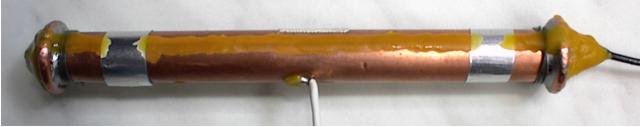
The thruster sealed with Bees wax ready to be filled with paraffin oil
The relative dielectric constant of paraffin oil is er=4.6-4.8. The thruster was mounted on the beam of the torsion pendulum and the voltage slowly increased until internal discharges were heard at the upper opening of the thruster at about 20 kV. The dielectric strength of the oil supposed to allow much higher voltage without discharge, but there must have been some tiny air bubbles trapped at the top of the thruster (below the wax plug), and this caused the early sparking. No thrust was detected in the 10-4-10-3 N range up till 20 kV using paraffin oil as the second dielectric.
The correct way of analysis that is in agreement with the
measurement results
The measurement results confirmed the validity of Newtons 3rd law in the thruster, but they also proved that the Coulombs law is not applicable on the charges of the dielectrics dipole-molecules when calculating the dielectrophoretic forces on the molecules.
Finding the correct formulas for the force components that would produce zero resultant thrust
Now we know that regardless of the dielectric constant of the
dielectrics and whether they are solid or liquid there is no resultant
unidirectional thrust on the thruster. This can happen in two cases:
The final formula of the first approach predicted too absurd results, thus we can cast away that method. Let us compare the formulas of the second approach for the EP force and for the dielectrophoretic CFE force:
The measurement results showed that when these two opposing components are added together, the resultant force will be identical with the Fep EP force in vacuum ie. when e =e0. If we divide the Fycm with 2 and add the two components together we get:
This is the correct formula for the resultant unidirectional thrust in a semi-cylindrical thruster segment that is independent of the applied dielectric, and it is identical with the thrust in vacuum. This is in agreement with the measurements. The influence of the dielectric on the thrust is neutralized by the fact that as much as the EP force increases due to increased permittivity, the opposing dielectrophoretic CFE force also increases in the same measure.
The next step is to find out how can we derive the correct formula that is only half of the originally calculated Fycm CFE force component. When the potential difference U between the electrodes is constant the E-field intensity can not be less than:
 because
and otherwise we would get less potential difference after performing the integral. From this follows that we can arrive to the correct formula only if the electric forces upon the charges of a dipole-molecule in solid and liquid dielectrics is not calculated with the officially accepted formula of F=Eq but with the modified formula: F=Eq/2. Let us perform the correct analysis of the CFE forces in the semi-cylindrical coaxial capacitor using this new formula.
The correct analysis of the CFE force in a semi-cylindrical capacitor
Let us calculate the magnitude of the resultant force component in the y direction, originating from these dielectrophoretic forces acting on the dielectric only between the electrodes. To accomplish this task we will have to know the attracting and repelling electrostatic forces upon the positive and negative charges of the elementary dipoles. Then by summing up these two opposing forces we get the resultant force upon the dipole. By integrating the elementary force components in the y direction over the whole volume of the dielectric, the macroscopic resultant force will be obtained. To perform these calculations, we have to know the magnitude of the equivalent dipole dp of an infinitesimal volume of polarized dielectric dV as the function of the local E-field intensity. In the case of linear isotropic dielectrics this is calculated as below:
The electric polarization represents the density of dipoles per volume
![]()
(where: n number of dipoles; V volume; N
density of dipoles; p- elementary dipole).
We get the
correlation between P and E as: ![]()
The dipole moment of an infinitesimal volume of dielectric is:
![]()
Now we can calculate the resultant electrostatic force upon a dipole.
Calculation of the CFE force upon the dielectric
The attracting and repelling forces upon the opposite charges of the dipole are:
The resultant force upon the dipole is:
Using the definition of the dipole: 
As the next step, knowing the equivalent dipole moment of an infinitesimal volume of polarized dielectric dp, and the resultant force upon such a dipole attracting it towards the smaller electrode:
The y component of this force (see figure) is: ![]()
By integrating these force components acting upon the infinitesimal volumes over the whole volume between the electrodes filled with dielectric we get the resultant macroscopic force in the y direction that we were looking for:
The negative sign means that the resultant force points towards the negative y direction (towards the smaller electrode). This is the same result that was demanded by the measurement results. If we add together the resultant EP force that acts on the electrodes of the semi-cylindrical capacitor (derived on page ethrform.htm) and the just derived FCFE dielectrophoretic force, we get the resultant unidirectional thrust that acts on the semi-cylindrical thruster (i.e. one half of the cylindrical thruster, when the thruster is closed):

This result shows that the unidirectional thrust upon one half of the cylindrical thruster is independent of the dielectric used between the electrodes, and it has the same intensity as if there would be vacuum between the electrodes. Consequently it is not possible to establish thrust asymmetry in a coaxial cylindrical capacitor using two (or more) different homogeneous isotropic dielectrics. This theory is in agreement with the above measurement results, wherein no thrust could be detected on a cylindrical coaxial capacitor filled with two different dielectrics. Analogous conclusions can be made for the spherical thruster using different dielectrics too.
The semi-charge model of dipole-molecules
The above measurement results and the new analysis led us to two
strange conclusions valid in solid and liquid homogeneous isotropic linear
dielectrics:
is not applicable for calculating the dielectrophoretic forces.
The inner half of the positive and negative charges facing within the molecule neutralize each other, and do not participate in the electrostatic force interaction with the outside macroscopic E-field. The discussed recognitions have some even more profound consequences and implications in the theory of electrostatics that will not be discussed here.
Created by Zoltan Losonc (feprinciples@on.mailshell.com) on 8 March 2004. Last updated on 8 March 2004.
|
Confirmed by SA&M |
|