Window solar air heater - Indoor to indoor airflow
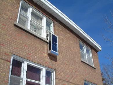
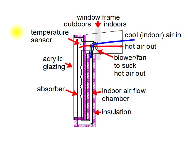
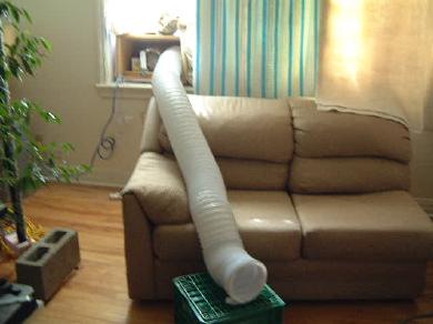
This was a modified version of my outdoor to indoor airflow solar air heater. Being in an apartment I was very limited in what I could mount on the building. So, just as many people place an air conditioner out their window during the summer, I designed a solar air heater that could be placed in a window during the winter without any modifications to the window. It would take indoor air, heat it with the sun and then bring it back into the apartment.
Since this is a modification of my outdoor to indoor airflow version, I'll leave common details such as the absorber construction and the electronics to that page.
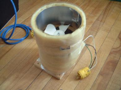
I tried to make all air flow pathways as big and rounded as possible so as not to restrict airflow.
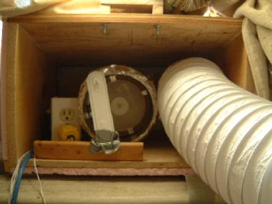
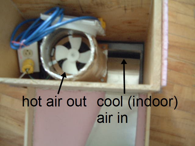
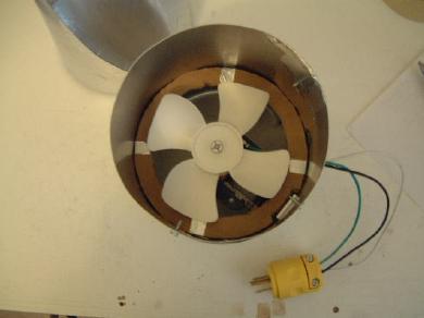
I also replaced the weak fan with a stronger one. From Home Depot, I purchased a JR-2 air booster fan, normally used in 6 inch ducts for increasing air flow. You can see it in the following photos and in the top-right one above.
I first tried with an AB-1 air booster squiral cage blower from Home Depot positioned such that it would push indoor air into the indoor air flow chamber but the airflow coming out the output was very weak (I made an adaptor so it could blow into the cool air in hole in the top-right photo above.) Changing it to use the JR-2 fan to pull air out, as in the above diagram and photos, resulted in stronger airflow being sucked into the input.
Testing
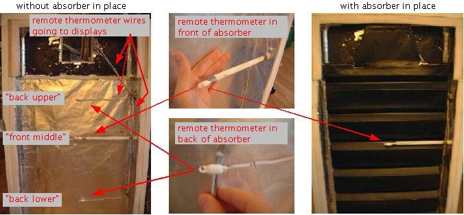
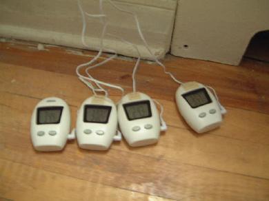
The temperature at a number of places was recorded. Especially handy for this were remote thermometers that consisted of a thermometer on the end of a 10 foot long wire with a display unit at the other end of the wire. See the photos below for how they were positioned. Also used were some regular mercury thermometers and local weather reports for the outdoor temperature.
With first, 11 indents aborber (more restricted airflow)
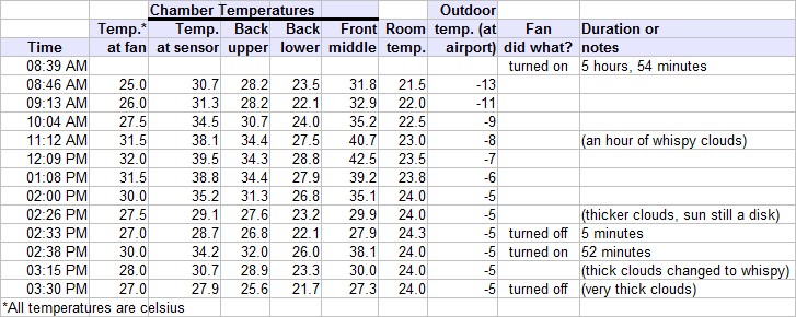
First, note that a new column, Temp. at sensor, has been added for the remote thermometer in the area of the temperature sensor. Next, notice that since there is no more outdoor air entering the bottom of the solar air heater, the air behind the absorber, the Back lower column, is much hotter. Notice also that whispy clouds in front of the sun (11:12am-12:09pm) don't cause it cool enough to turn off and that even thicker clouds take some time (2:26pm-2:33pm). And lastly, the temperature at the sensor (Temp. at sensor) that causes the sensor to turn off the fan is around 28C (2:33pm and 3:30pm) and it turns on again at around 34C (2:38pm).
With new, 4 indents absorber (less restricted airflow)
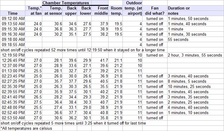
With the new absorber, air flow was faster through the unit. This can be seen by the frequent on/off cycles where the temperature at the sensor (Temp. at sensor) would reach around 36C, turn on the fan causing the flowing air to take the heat from the absorber, causing the temperature to decrease to around 30C, at which point the sensor would turn off the fan, letting the absorber heat up again and the cycle repeat. This means that less indents in the absorber allowed for higher air flow, which cooled the absorber faster.
However, notice from the Room temp. column that even though 24C to 27C air was entering the room (Temp. at fan), the room did not heat up. This was true even between 12:19:50pm and 2:23:45pm when the fan stayed on the whole time. This means that a larger absorber is needed in order to gather more heat from the sun while still maintaining a high air flow.
As a side note, notice that temperature sensor did act a little strange as between 12:26:45pm and 2:23:45pm, it would not turn off the fan until the temperature at the sensor reached 26C. Before that, it would do so around 30C. Also odd was that it slowly corrected itself and resumed turning off around 30C and on around 36C at 2:52:40pm. But as I said above, this was just a cheap $5.00 CDN sensor.
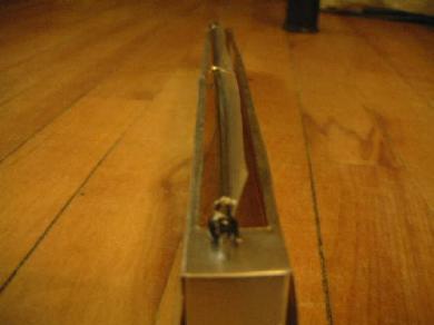
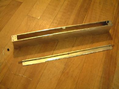
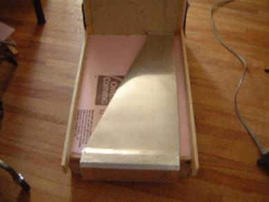
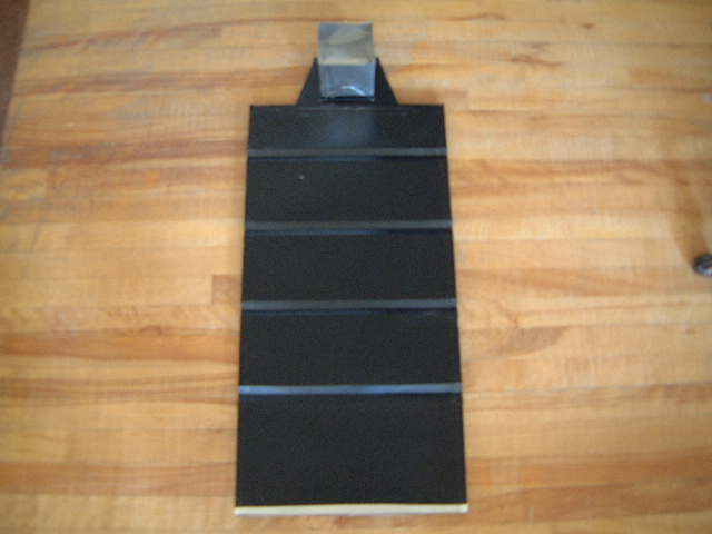
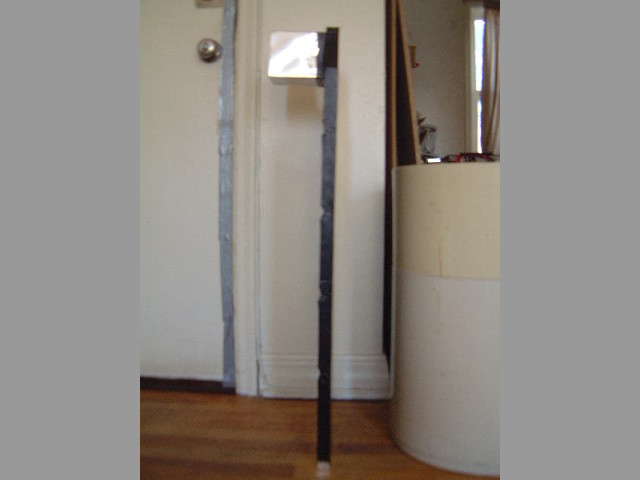
A damper for the bottom
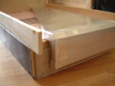
The following two photos show a damper I made for the putting inside the absorber at the bottom. The idea was that when the temperature sensor determined that the air in the absorber was hot enough, the fan would turn on and suck the hot air out of the absorber and into the room. This suction would also pull the damper open, allowing cool outdoor air into the bottom of the absorber. Once the temperature sensor determined that the air in the absorber was cool again it would shut the fan off and the damper would fall closed again preventing more cool air from entering the absorber and allowing the air already in it to heat up quicker.
I found that there wasn't enough air flow in the incoming air to make the damper open. In fact, the air flow was so small that it just flowed around the gaps in the damper. Removing the damper made no difference in the results so I ended up not using it.