Before assembling my probe I did some preliminary tests to see if the
resistors would hold up. The highest voltage I could measure before
my power supply arced was 46kV. This was a little disappointing since
my power supply was supposed to put out between 50kV and 150kV.
Instead the initial reading on the meter was about 28kV and as I said,
it arced at 46kV. The spark length is not a reliable measure here since
the diameter of the spheres (2.2 cm) on either side of the spark gap was
significantly smaller than the gap size (4.1 cm). So either there is a
problem with my probe setup, there is substantial leakage, or my supply
doesn't put out as much as I thought. There was some leakage as
hissing was heard from where connection was made to the power
supply. Using a simple 6V battery, through the probe it reported
6.0V (.0060Vx1000) but without the probe it reported 5.5V. I'm not
sure what to think of that difference (see July 17th entry below for
the solution).
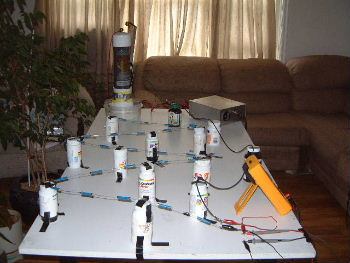
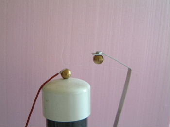
Diagonal view of the test setup. The resistors are
soldered together.
 |
|
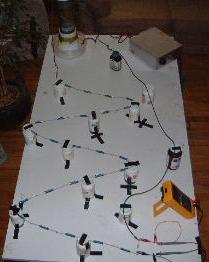
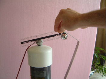
Top view of the test setup.
 |
|
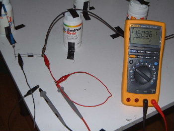
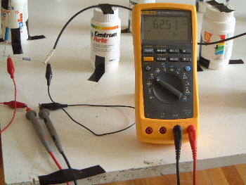
DMM connections and reading of 46.096V which x1000 is
46kV (actually the meter says -46.096V. I just noticed I had the meter hooked
up backwards, red to ground). Arcing occurred at the power supply after
this voltage.
 |
|
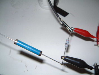
Closeup of a 200M ohm resistor (blue) and the
10M ohm resistor. The black and red clips across the 10M ohm resistor
are going to my meter.
 |
|
I realized that my arcing was probably being caused prematurely
by leakage at the spark gap at the power supply (see pictures below).
I figured that leakage there would create an ionization path in the
air between the balls and cause arcing at lower voltage than one would
expect given the gap size. So I tried a number improvements until
finally I could turn my power supply's variac up as far as its stops
would allow it to go without arcing. This gave me 62kV on the meter
with an arcless spark gap of 7.2cm.
These are the old 2.2cm diameter copper balls
that came with the power supply when I purchased it 6 or 7 years ago.
The first improvement I made was to use aluminum tape to cover and tape
the wire to the back of the ball. Previously it was just wedged below
the ball. This got me from about 46kV to 51kV (I wasn't too careful
about maintaining the spark gap size between measurements).
 |
|
I next replaced the balls with these 2.9cm diameter
steel balls. This got me from about 51kV to 58kV despite the decreased
spark gap between them.
 |
|
I kept increasing the spark gap by random amounts
(i.e. not by careful increments) until I could turn the power supply
up all the way that the stops on the variac would allow with no arcing.
At this point I also improved and taped up the other sources of leakage
though they still leak.
 |
|
After all these improvements, I managed to measure
62kV on the meter (notice that I've also reversed the meter probes so
that black is connected to ground and red to the positive side of ground).
 |
|
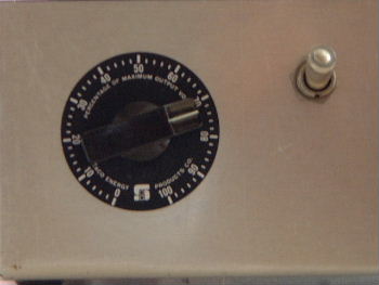
Here is the maximum setting that the stops
allow me to turn the dial to. These stops are just epoxied in place
on the inside of the case.
 |
|
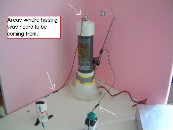
Here are the three areas where hissing is still
heard to be coming from.
 |
|
When doing my battery test on July 12 (see above) it turns out I
was using the wrong range on my meter when meassuring
through the resistor network and therefore getting less accuracy.
I switched from the DC V range to the DC mV range and the meter
was now giving me around 55mV (1000th of the value without the
resistor network).
At Zoltan Losonc's suggestion I measured the AC power line on
my DMM and got around 118V. I then measured through my resistor
network and measured around 470mv (milli, not micro) but it seemed
to change a lot. It would start around 470mV then steadily decrease
until I pulled it out and put it back in again.
Again at Zoltan's suggestion, I then removed the 10M ohm resistor
that was in parallel with the DMM and replaced it with my oscilloscope.
It turns out that my resistor network as laid out on the table as it
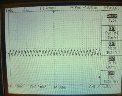
is is acting as an antenna. It's picking up the 60Hz signal. When
the ends of the reistor network are not connected to anything I get
around 210mV RMS at around 60Hz (see 1st picture below). When I connect
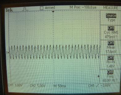
the ends to the power lines I get an RMS that fluctuates between
around 470mV to 490mV RMS at around 60Hz (see 2nd picture below).
Note: after taking these pictures and loading them into the computer
I had the idea of improving my connections to the power lines by
adapting an old plug. The values I now get are different but still
demonstrate the antenna behaviour. Even with the camera in place
with its extension chord I see a slight change on the scope.
I don't think the values are so important as the fact that the
resistor network, when strung out like this, is picking up an AC signal
that needs to be eliminated either through sheilding, shape of the
network, or something.
Note that during the measurements below, the reading on the
DMM matched the RMS on the scope.
With end of the resistor network not
connected to anything.
 |
|
With end of the resistor network connected
to the power lines.
 |
|
The Input Impedance, DC Coupled, for my scope is 1Mohm +/-2% in
parallel with 20pF +/= 3pF and its maximum voltage is 300V RMS.
However, I'm using a X10 probe with the scope which has a
9Mohm resistor for a total of 10Mohm impedance. This means I
can put my scope in place of my DMM and make measurements.
My only concern was damaging the much more expensive scope but in
my desire to get on with it, I took a chance. Good thing I did too.
Speaking to the maker of the power supply (Information Unlimited),
he said that under no load the output should be fairly flat DC and
that under load there will be more ripple. With a high frequency
output there would be issues with using my simple probe with my
scope but since it's fairly flat DC the combination should work fine.
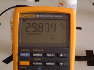
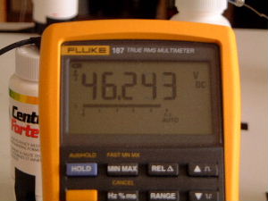
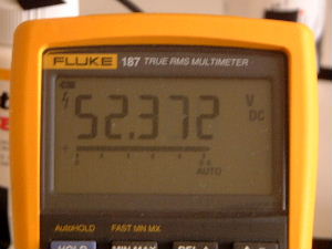
I made 3 sets of measurements: 29kV, 46kV, 52kV. For each one I
made a simple voltage reading with the DMM, turned off the power supply
without touching the dial on the power supply, discharged the power supply,
replaced the DMM with the scope, turned on the power supply, and made
various measurements on the scope. The scope and DMM voltage measurements
matched.
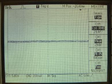
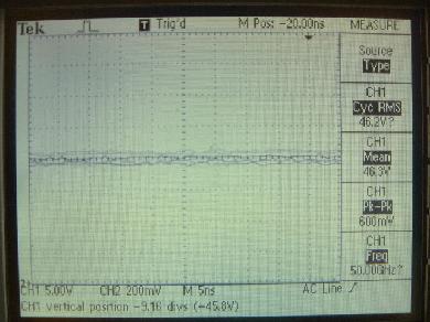
Using the scope, I noticed that each voltage had two AC waves riding
on it. A 60Hz, 2V (2kV) (approximately) wave and a 12kHz, 4V (4kV)
(approximately) wave. Note that the voltage values on the scope should
be multiplied by 1000 to get the actual kV values as I've done in
the previous sentence.
Neither wave seems to change in either amplitude or frequency with
different power supply voltages. This means the higher the voltage,
the less the effect these waves will have on measurements. I'm guessing
the 12kHz is power supply ripple. I would have suspected that the
60Hz was because my HV probe is acting as an antenna but 2kV is a bit
much unless it is being amplified somehow by the power supply meaning
that some or all may actually be from the power line feeding into
the power supply.
Note that this was all done with no load on the power supply.
The following pictures illustrate all of this.
29kV measurements
|
|
|
|
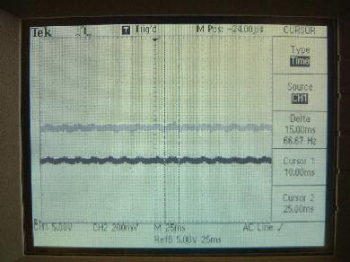
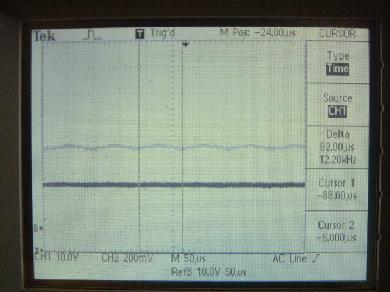
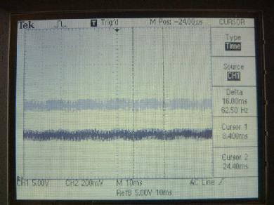
In the following pictures, note the vertical cursors measuring time
and the resulting Deltas on the right. The top grey wave is a saved one,
the bottom darker wave is the active one. I had to save one as the wave
was fluctuating too much to observe.
|
|---|
Approximately 60Hz
 |
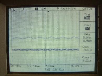
|
Approximately 12kHz
 |
|
46kV measurements
|
|
|
|
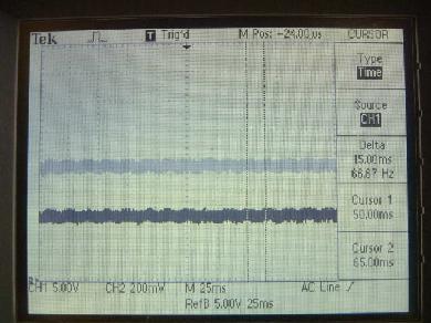
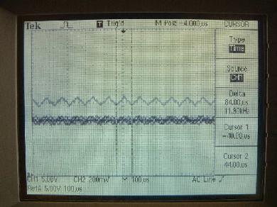
In the following pictures, note the vertical cursors measuring time
and the resulting Deltas on the right. The top grey wave is a saved one,
the bottom darker wave is the active one. I had to save one as the wave
was fluctuating too much to observe.
|
|---|
Approximately 60Hz
 |
|
Approximately 12kHz
 |
|
52kV measurements
|
|
|
|
In the following pictures, note the vertical cursors measuring time
and the resulting Deltas on the right. The top grey wave is a saved one,
the bottom darker wave is the active one. I had to save one as the wave
was fluctuating too much to observe.
|
|---|
Approximately 60Hz
 |
|
Approximately 12kHz
 |
|