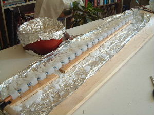
July 26, 2003 - Soldered resistor chain into final form
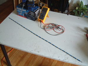
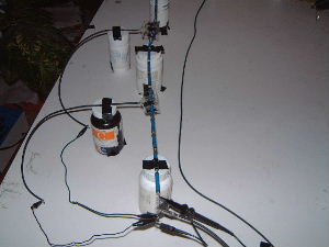
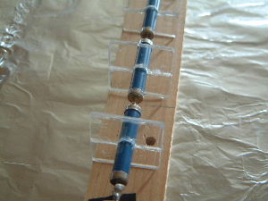
I spent the day soldering the resistor chain together into its final form. The total length (including the 10Mohn resistor) is 1 meter and 8 cm with the gaps between resistors being anywhere form 5mm to 7mm.
Notice in the pictures below that I used two vises to hold the resistors while I soldered them. Originally I had the spacing between resistors at about 1cm so that I could attach the tips of needle nose pliers to either end to act as heat sinks, the purpose being to protect the resistors. However, in my first attempt the solder attached to the pliers so I gave up on that approach. It turned out that the vises themselves acted as perfectly good heat sinks allowing me to use a smaller spacing. I soldered the resistors into three chains of 7 and one chain of 4. The final assembly was done by taping the chains to the table surface and soldering the joints without heat sink. I guess the use of the vises was a bit of overkill. Despite the heat from all the soldering not one one resistor was ruined.
|
|
|
August 4, 2003 - Corona gap progress
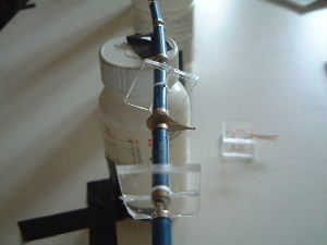
I made a few attempts at building a corona ring but couldn't figure out any way to build it such that I could position it at location 5 along the chain and then reposition it at location 1 and still have the same distance between the ring and the resistor contact. Some pictures of what I tried are below.
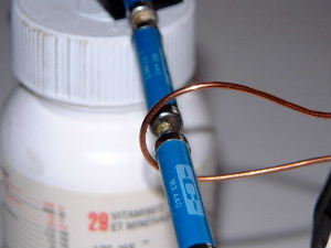
What eventually worked out was to just have a single solder bulb instead of the ring. Also, rather than using the point at which I soldered the resistors together as the other side of the corona gap, I ended up using the much more consistent outer corner of the endcap on the resistor itself. Corona would therefore form between the solder bulb and the endcap. I confirmed this in the dark but unfortunately my camera is incapable of taking pictures at that light level.
Pictures of my attempts with a ring
|
|

|
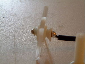
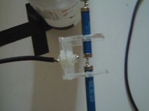
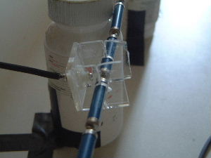
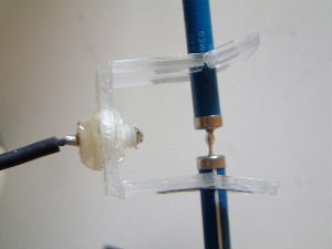
A solder bulb instead of a ring
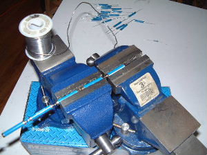
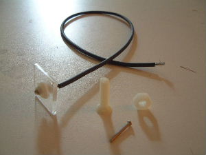
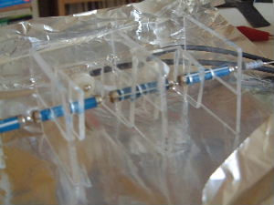
There were a couple of advantages to using a solder bulb. The first is that I was able to make an adjustment screw that I could use to move the bulb closer out or farther in. The second is that the resulting structure could be pulled off the resistors at location 5 and put on the resistors at location 1 and be sure that the gap is the same at both locations.
As shown in the pictures below, the solder bulb assembly is made up of a nylon bolt with a smaller metal bolt screwed through the middle of it. The head of the smaller bolt is where the solder bulb is (solder was melted onto it). The other end of the smaller bolt is where the wire is attached. The clear glass-like piece is a 1"x1" piece of lucite. A 1/2" hole was drilled through the middle of the lucite piece and a nylon nut was epoxied into the hole. It is this nut that the nylon bolt is screwed into.
|
| ||
|
| ||
|
|
August 11, 2003 - Corona gaps finished
As per Zoltan's advice I set the size of the second corona gap (the one further from the meter) such that it would leak before the first one.
|
|
|
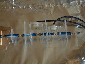
August 11, 2003 - Stand-offs attached
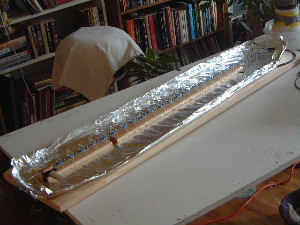
In order to center the resistors in the final PVC tube I had to put lucite stand-offs around them.
|
|
|
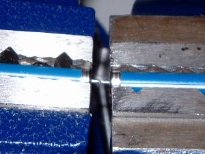
August 11, 2003 - Probe tip made and attached
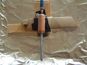
The probe tip was made to be fairly leakless and interchangable. The supporting part is a .5" diameter copper rod with a tapped hole in it. The actual tip is a bolt that I filed and then sandpapered down to a rounded tip. The threads on one end were left alone so that it could be screwed into the copper rod.
|
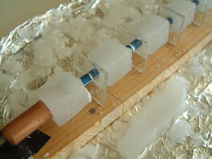
August 23, 2003 - Waxing the connections
To prevent ion leakage at the connections between the resistors I kept the connections as short as possible, used large rounded bulbs of solder and applied paraffin wax. I first tried just dripping wax on but that created layers and flaked off fairly easily under stress. So then I made a small rectangular mold which I alternately put in place around each connection and poured wax into. This made a nice rigid, uniform block of wax that held on tightly. The pictures below show the results after a week of pouring (evenings).
|
|