Construction of Homemade High Voltage Probe (> 40kV) - Page 3 of 3

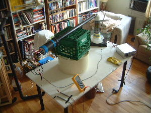
August 24, 2003 - PVC tube construction and chain insertion

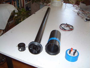
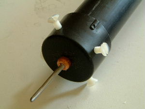
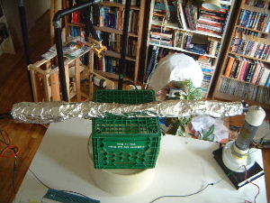
The final step was to make a tube out of PVC tubing that the resistor chain could slide into and be secure.

The tube was made of four components. Going from left to right they are: the endcap for the probe tip, the long narrow tube for most of the chain, the short thick tube for the part of the chain that has the corona gaps and the end cap with the connectors. Also shown in this picture are some banana plug patch cords.
Construction details of the part of the long narrow tube that connects to the short thick tube. The wider disk screws into the short thick tube. I epoxied these two parts together and then added the plastic L parts for added safety in case the epoxy ever fails. I used nylon bolts to bolt the L parts into place (epoxy didn't work well for this).

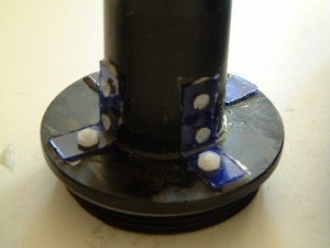
In hindsight (thanks to Zoltan for pointing it out) I should have used PVC glue instead of epoxy. "The special PVC glue is not more expensive than the epoxy and usually it can be acquired from stores where the PVC pipes are sold. The epoxy does not make a very firm bound with the PVC. But the special PVC glue makes a perfect `welding' because it is made of the same PVC material solved up by some chemical. When the solvent evaporates, a perfect bond remains since the `glue' now became the same PVC as the pipes have been made of." - Zoltan. I would still have added the L parts (or PVC triangular pieces) for extra safety.

Carefully inserting the chain into the long tube. Note that I'd already soldered all the wires onto the chain.
I then screwed on the short tube.
I then slid the probe tip endcap into place and tightened the nylon bolts. The nylon bolts make contact with the .5" copper rod and hold it firmly in place.

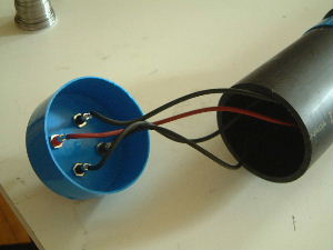
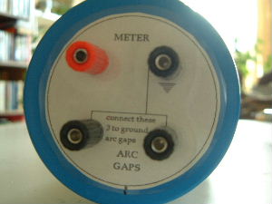
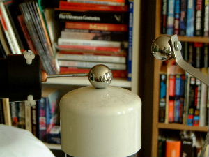
I was probably being silly but I decided to have separate connectors for the ground wires coming from the corona gaps and have these separate from the connector for the probe ground. Really these wires should probably all be soldered together and I should have just one ground connector.

I soldered the wires to the connectors on the endcap.
View of the endcap in place. Note the separate connectors for each corona gap (labelled as ARC GAPS).

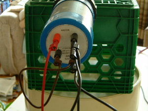
August 24, 2003 - Testing

Note the complicated wiring using banana plug patch cords. The reason is that I'm plugging the two ARC GAPS together and then plugging them with the ground plug. The end result is just two ends for connecting to the meter.
The probe in place for testing. During the test everything was quiet, all the way up to 75kV (see scope tests below)! Practically no leakage since all HV connections were either insultated or not leaky. It was very spooky to watch a system with such high voltage be so quiet.
The probe tip in contact with the positive ball on my power supply. Note that I've bent the attachment to the ball on the right so that the bar is no longer on top of the ball.
75kV with no hissing or clicking but with some high frequency sound.
Another measurement of 75kV, different sampling rate.

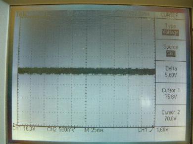
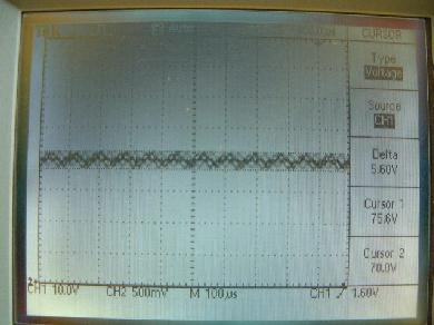
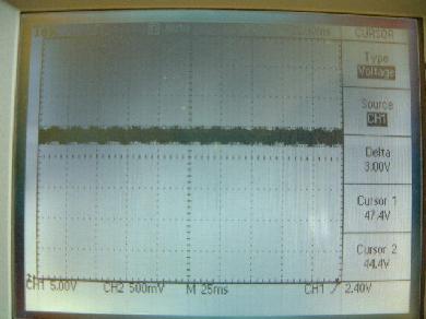
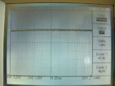
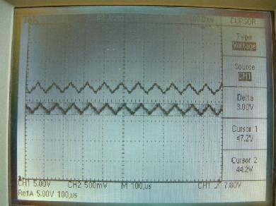
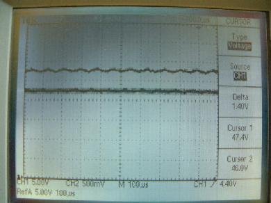
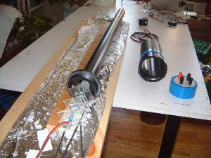
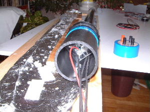
At Zoltan's request I tested how much of the 60Hz signal I would see with the probe shielded (wrapped in grounded aluminum foil). I expected to see no change since I was expecting most of it to come from the other wiring in the system. I was wrong. As the probe snapshots below show, most of it disappears. Note that the 12kHv signal is still there. Note also that with the foil I could go only up to around 50kV before the edge of the foil nearest the probe tip arced with some part inside the probe (probably the copper rod). So measurments below with foil have been restricted to 47kV.

Probe wrapped in grounded aluminum foil.
The 60Hz signal without the aluminum foil shield (cursors measuring peak to peak).
The 60Hz signal with the aluminum foil shield.
The 12kHz signal without the aluminum foil shield. The top trace is a saved one. The bottom trace is the live one.
The 12kHz signal with the aluminum foil shield.
rimstar.org
Contact:
Liked this? Share it with: