This was an attempt to make a UHF oscillator, specifically one that oscillates
in the hundreds of MHz range and eventually one that is tunable around 300MHz.
The purpose was to use it as a starting point for developing a frequency source for the
testatika Linden experiment
under the assumption that the experiment's long wire is a lecher line
that is 1 metre long, the wavelength corresponding to 300MHz which in turn
corresponds to the speed of light (approximately 300,000,000 metres/second.)
The source for the design is
this UHF oscillator here. I first noticed it because the author
used it to demonstrate
measuring the frequency of a lecher line here. From my understanding it is
basically a resonant LC circuit where the inductor coil (the L) is a single turn and
the capacitor (the C) is needed to be so small that it is provided by the
capacitance of the circuit and the transistor. Amplification is then provided
by a 12volt power supply.
As the testing section below states, I did not have any success making this
work. I'm not an electronics expert and have reached the end of my analysis
abilities. Any help would be most welcome.
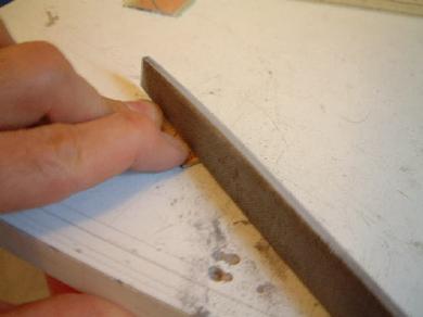
Construction of the UHF oscillator
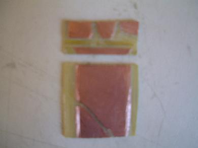
The backing was made by taking single sided PC board, scraping away the unwanted
parts and assembling the results along with supports and sockets for the antenna...
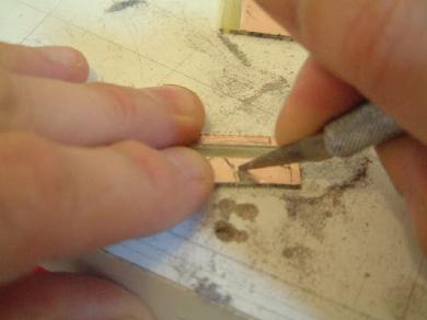
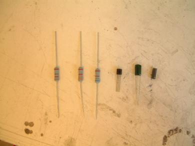
Next, the components were soldered on...
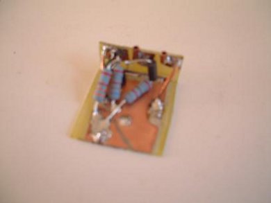
From left to right: 820ohm, 3300ohm and 6800ohm resistors,
NTE107 high frequency UHF transistor (replacement for C717), 1nF capacitor,
ferrite bead.
 |
|
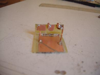
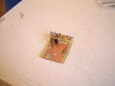
The capacitor and transistor in place.
 |
|
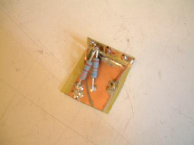
The 3300ohm and 6800ohm resistors in place.
 |
|
The 820ohm resistor with the ferrite bead on one leg.
 |
|
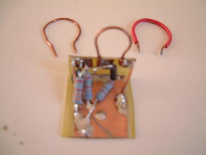
The end result with single turn coil in place. Other
coils that were tried are included.
 |
|
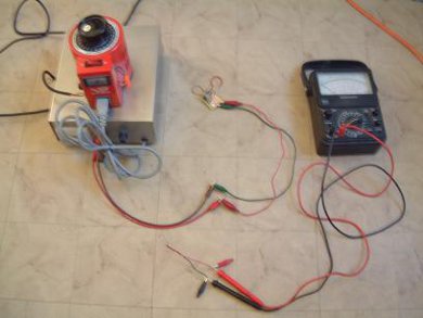
Testing the UHF oscillator
The following photos illustrate the testing. With the analog meter on the
1VDC scale, the needle did not move at all. One thing that may or may not
be a clue to the problem is that after the
12V power supply is turned off at the end of
the test, the voltage meter on the face of the power supply does not immediately
drop to 0V but instead slowly drops to 0V over about 30 seconds, indicating
that the voltage is being held somewhere or there is no load to dissipate it.
Three different coils were tried: 15mm diameter, 22mm, 25mm. Also, two
different transistors were tried:
- NTE107 (replacement part for C717) - T-NPN, Si, High Frequency UHF,
VCBO=30V, VCEO=12V, VEBO=3V, IC=50mA,
PD=200mW, hFE=75 Typ, fT=1000MHz Min
- NTE123AP - T-NPN, Si, Amp, Audio to VHF Sw (Compl to NTE159),
VCBO=75V, VCEO=40V, VEBO=6V, IC=600mA,
PD=625mW, hFE=200 Typ, fT=300MHz Min
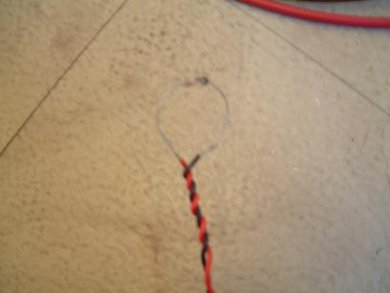
The diode used in the pickup loop (see photos below) is NTE109 - Ge. General Purpose
Diode Fast Switching, PHV=100V Max, IF=60mA Max,
IFSM=500mA Max, VF=1V @ 200mA.
|
|
The diode on the pickup loop which is connected to
the analog meter probes.
 |
|
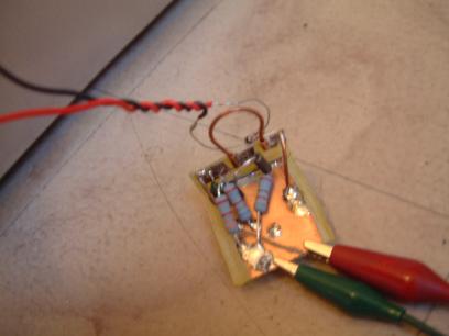
The pickup loop being held near the single turn coil,
hoping for inductance.
 |
|