Results
The dielectric constant as determined by the method below is: 3.5.
3.5 is the capacitance of the resin capacitor (0.053 nF) divided
by the capacitance of the air capacitor (0.015 nF).
The test was made using a parallel plate capacitor where the plates
were aluminum. The spacing
between the plates was 7.5mm. To calculate the dielectric constant
two capacitors were made: one with resin for the dielectric,
the other with air for the dielectric. The dimensions of the resin was
122mm x 122mm x 7.5mm. The air gap for the air capacitor was 7.5mm.
The
capacitance of each was measured using the capacitance measuring feature
of a Fluke 187 True RMS Multimeter. The measurements made are
detailed in the pictures below.
The resin was warped (i.e. not a perfect block) due to the way it was
made. However, the thickness was very close to 7.5mm throughout.
Aluminum foil was used for the electrodes so that they would follow the
shape of the resin, adhering closely. The dimensions of the
aluminum foil was 101.6mm x 101.6mm. The thickness was not known but
it was fairly thin foil purchased in a grocery store.
The electrodes for the air capacitor were aluminum of dimensions
.8mm x 101.6mm x 101.6mm.
The orginal test setup had the foil taped to the resin with small
pieces of tape and nothing else pressing the foil to the resin.
However, this left subtle wrinkles and hence air gaps between the resin
and the foil. With this the dielectric constant was 3.2 (0.0485 nF
divided by 0.015 nF). Zoltan Losonc then suggested the method used
below of pressing the foil firmly against the resin.
I deviated from what he suggested only in that I found and used foam
rubber whereas he had suggested using sponge.
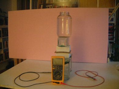
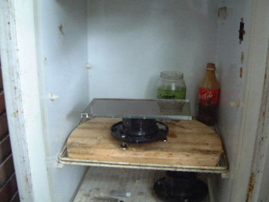
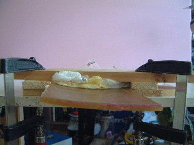
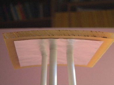
The setup for measuring the capacitance of the resin.
The resin is the brownish horizontal slightly curved line visible just above the meter.
The large bottle on top is filled with water in order to press down
firmly on the whole setup.
 |
|
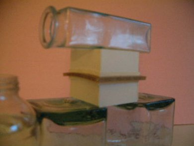
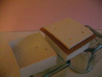
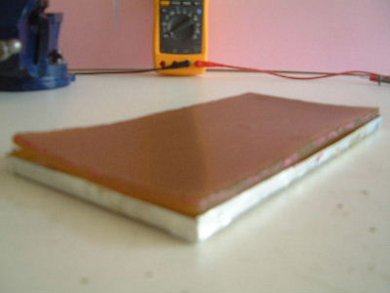
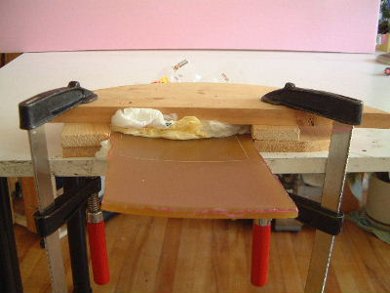
A closer view of the resin sandwich. On the top
and bottom of the resin are the thin foil electrodes. Then the 1/4 inch thick
foam). Pressing in on that from the top and bottom are some plastic "boxes".
The sides of
the plastic bozes facing the resin are shaped to match the shape of the
resin so as to push the foam evenly against the resin and hence the electrodes.
 |
|
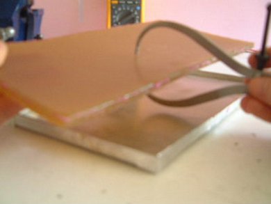
The top box removed so that you can see the piece
of foam that is sitting on the top electrode (hidden by the foam).
Note the holes in the foam and in the corresponding positions in the
box. These are to admit the probes from the meter. There is one hole
in each quadrant so that measurements could be made in 4 locations.
 |
|
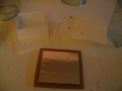
Another view showing all the pieces.
 |
|
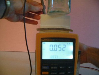
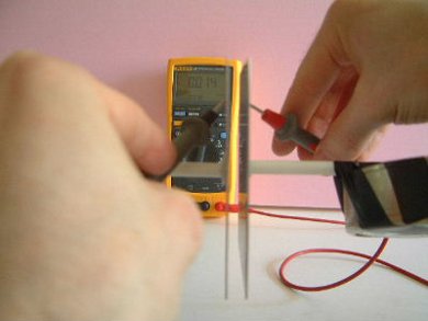
Making the measurements. Note my hands holding the
probes in the boxes. The probe tips are going throught the holes described
above and are touching the electrodes (foil). The measurement varied from 0.052 nF...
 |
|
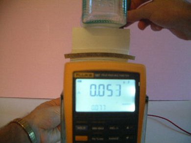
... to 0.053 nF with 3 of the 4 measurements being 0.053 nF.
Note that prior to making the first measurement, the meter was zeroed (put in
relative mode). The capacitance on the meter before zeroing was 0.077 nF (visible
in the bottom of the display).
 |
|
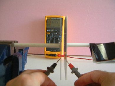
Air capacitor
Capacitance on meter when not measuring capacitor is 0.078 nF.
 |
|
The measurement varied at different points from 0.014 nF...
 |
|
... to 0.015 nF. Most were 0.015 nF.
 |
|
Construction
Making rectangular blocks of resin is hard. First the resin is poured and
then drops of hardener are added. Hardening takes from 30 minutes to 2 hours
depending on how much hardener is put in. During the hardening the
resin heats up tremendously. And the more hardener you put the hotter
it will get though the faster it will harden.
Due to the heat generated during hardening you have to choose the
material for your mold carefully. The heat will melt some plastics.
However, the amount of heat seems to be dependent on the amount of hardener
you put. The more hardener the hotter it is. I used aluminum for this
mold. Also, to hold the sides of the mold together I used aluminum
tape. Black electrical tape will melt or get sticky and loose allowing
the sides of the mold to open up and leak. Aluminum tape doesn't
seem to have this problem much.
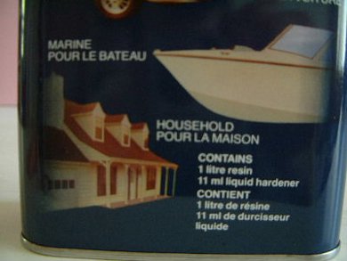
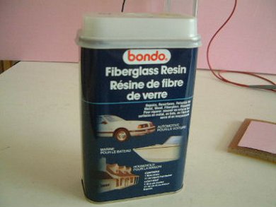
The container for the resin.
 |
|
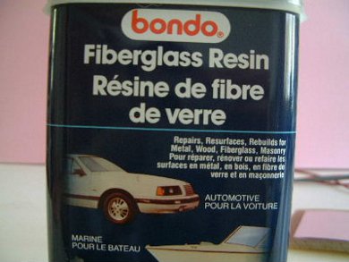
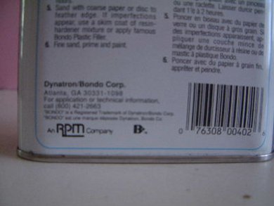
The resin used was Bondo resin, of Dynatron/Bondo Corp.
The address on the back of the container is Atlanta, GA 30331-1098 (USA) and
the phone number is 800-421-2663.
 |
|
|
|
|
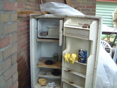
Resin is toxic so I worked outside in my Resin Construction Unit :->
 |
|
The resin hardening in the mold. Note that the base
under the mold has adjustable legs. A small level was put in the mold and
the legs were adjusted to make it level.
 |
|
The end result was warped...
 |
|
... but fairly uniform in thickness throughout.
The area that was most uniform was selected and cut out.
 |
|
To cut it out it had to be held rigidly in place. So
I set this up, basically wedging it in crumpled up plastic bags.
 |
|
Another view. You can see the area I selected (see
the scratched lines).
 |
|
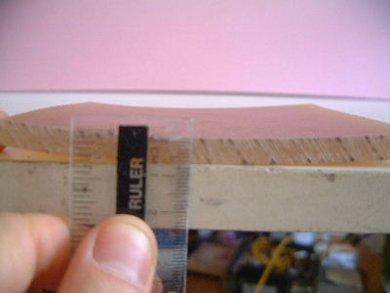
Side view showing how uniform in thickness it is.
At most locations on the side it was 7.5mm thick though in one corner it
was closer to 8mm and at points it was closer to 7mm.
 |
|
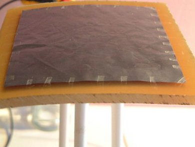
The finished result with foil - top view. 32 pieces
of scotch tape (clear tape) were used to hold it in place.
The tapes were about 2mm x 12mm each. Note the darkness at the edge
that is really the shadow of the bottom foil caused by the lighting.
The light is on the right.
 |
|
The finished result with foil - bottom view. 13 pieces
of scotch tape (clear tape) were used to hold it in place.
The tapes were about 2mm x 12mm each. The shadow is less clear here
due to the different lighting from this direction. The light is on the
right.
 |
|