Mini solar air heater
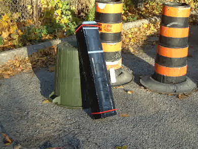
The idea was to build a prototype solar air heater based on the principles of the Cansolair just to try it out. From the testing below you can see it was quite successful.
The solar heater parts
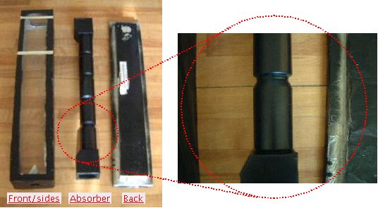
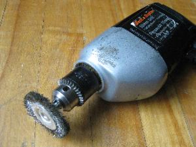
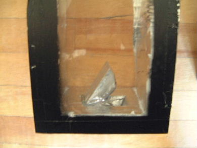
The absorber is a stack of pop/soda cans. The original paint was first stripped off with a wire brush attached to a drill. Sanding by hand with sandpaper took too long. Then tops were cut out. The bottoms were not. Instead, as the following picture shows, a pattern was cut into the bottoms and the metal bent back in such a way that any air moving through the hole would spin and move outward against the insides of the cans in order to capture more heat.
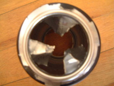
The cans were then taped end-to-end with plumber's aluminium tape. The two chambers at either end of the stack were just aluminium flashing bought from a local hardware store (Canadian Tire), cut and aluminium taped into shape, and then taped to the ends. The complete stack was then painted with flat black spray paint normally used for painting radiators and barbecues. The idea was that this paint would be able to take the heat.
The glazing is just 1/8" thick acrylic. Three pieces were used because that was what was on hand.
The sides and back are 1" thick pink rigid extruded polystyrene, which also just happened to be on hand. No wood was needed and the polystyrene was rigid enough to serve as both insulation and structural support. The problem with this material, though, is that it can off-gas formaldehyde when exposed to sunlight and possibly extreme heat. It is also highly flamable. But, since this was just a prototype, it was used. All the polystyrene was covered with aluminium foil and with the same flat black paint as the absorber.
The flat black paint stuck well to the aluminium cans, maybe because their sides were roughened, but it tended to flake off of the aluminium foil.
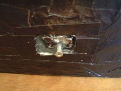
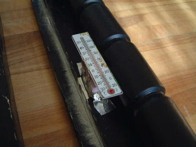
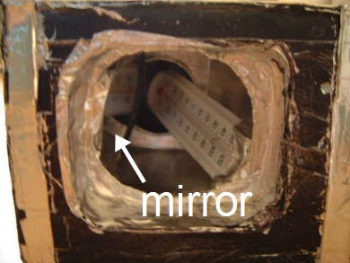
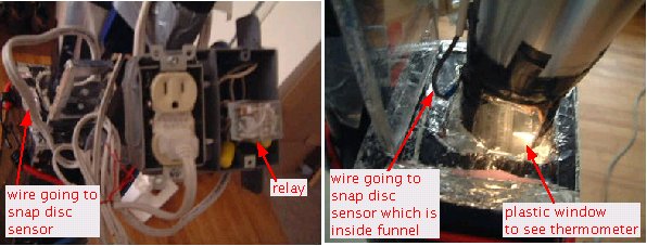
Two thermometers were embedded in the prototype. In the left photo above is a thermometer that lives outside the absorber but in the air chamber just behind the acrylic glazing. In the right photo is a thermometer inside the top chamber just above the can stack. To read it, it was necessary to also embed a mirror. In the photo on the left, the front/side piece is not in place, whereas in the photo on the right, it is.
Testing
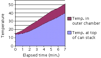
The outdoor ambient temperature in the sun was 16C (60F). The top and bottom were opened up so cold air could flow into the bottom and hot air could flow out from the top, hopefully doing thermosiphoning. A small 30W fan was brought out to suck the air out. That couldn't be arranged well so an electrolux vacuum cleaner was brought out instead since the hose could be wedged into the top. With the top still open, the outer chamber heated up to 50C (122F) within minutes. The vacuum cleaner hose was put in place and the temperature inside the can stack was lowered. But the heat of the outer chamber would quickly heat up the can stack again.
| Time | Elapsed time (min.) | Temp. at top of can stack | Temp. in outer chamber |
|---|---|---|---|
| 12:40pm | 0 | 14C (57F) | 15C (59F) |
| 12:41pm | 1 | 15C (59F) | 19C (66F) |
| 12:42pm | 2 | 18C (64F) | 25C (77F) |
| 12:43pm | 3 | 22C (71F) | 30C (86F) |
| 12:44pm | 4 | 27C (80F) | 36C (97F) |
| 12:45pm | 5 | 31C (89F) | 42C (108F) |
| 12:46pm | 6 | 35C (95F) | 46C (115F) |
| 12:47pm | 7 | 40C (104F) | 51C (124F) |
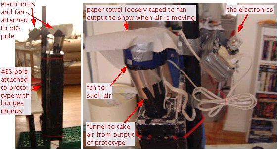
The electronic parts
Next, electronics and a fan were needed. The fan sucks air out of the solar air heater and so is at the top. But the fan should turn on only when the air in the can stack is hot enough and turn off then it's cooled down again. This is very simply done through one simple electronic component, a bimetal snap disc thermal sensor. See how to use it in this electronic temperature control circuit. The following photos show the result. WARNING: The following photos contain electronics arrangments that are extremely ugly. :-)
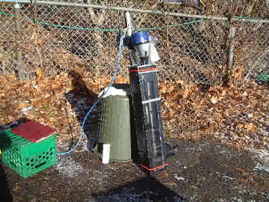
Testing the electronics
The outdoor temperature in the sun was -1C (30F).
| Time | Fan did what? | Temp. at top of can stack | Temp. in outer chamber |
|---|---|---|---|
| 12:12pm | Turned on | 49C (120F) | 49C (120F) |
| 12:28pm | Turned off | 26C (79F) | 32C (89F) |
One nice thing was that a temperature of 49C (120F) could be reached. This is a 50C (90F) rise above the ambient. This means the insulation was doing its job and there was little loss through the acrylic glazing. Once the fan started, it took 19 minutes for the temperature in the cans to drop by 23C (41F).
