Sizing the solar array for you off-grid solar power system
The next step is to figure out which solar panels (also called solar modules) you need and how many. For an off-grid system you'll likely need more than one solar panel. The collection of all your panels is referred to as your solar array.
Solar panel specifications
Solar panels are specified by a few values which can be found on a label on the back of the solar panel (see photos below) or by searching on the internet for the panel's manufacturer and model number. The values are obtained under certain standard test conditions (at sea level, a certain temperature and amount of sunlight) and will not reflect what you'll actually get at all times.
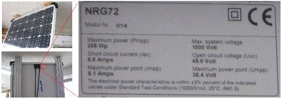
The important values are:
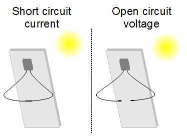
- Short circuit current (Isc) - This is the
current when both ends of a solar panel are directly connected
together. In the diagram above there is no
load in this case; the two output wires in the back of the solar
panel are connected to each other.
The "I" in Isc stands for intensity and is an old word for current. The "sc" stands for short circuit, which is what it's called when the two wires of an electrical circuit are connected together with no load in between. - Open circuit voltage (Voc or Uoc) - This
is the voltage measured when nothing is connected to the solar panel
i.e. no electrons are flowing, there is no current. In the diagram
above the two output wires in the back of the solar panel
are both not connected to anything. A solar panel's voltage is at
a maximum when there is nothing making demands on it, or in more
technical terms, when there is nothing drawing current from it.
The "V" or "U" in Voc or Uoc stand for volts and "oc" stands for open circuit, the circuit is open with nothing in between the two ends. - Maximum power current (Imp or Impp) - This
is the current the panel has available when the panel's power output
is at a maximum under certain standard sunlight and temperature
conditions. See immediately below this list for more about this.
The "I" stands for intensity and is an old word for current. The "mp" or "mpp" stand for maximum power or maximum power point. - Maximum power voltage (Vmp, Umpp, ...) - This
is the voltage the panel produces when the panel's power output
is at a maximum under certain standard sunlight and temperature
conditions. See immediately below this list for more about this.
The "V" or "U" stands for volts and "mp" or "mpp" stand for maxium power or maximum power point and there can be other variations of these letters.
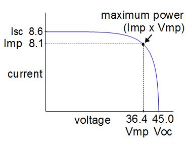
Maximum power point graph.
Maximum power current and maximum power voltage are related and exist at the same time, when the power is at a maximum (see the graph above.) That's because the power is equal to the current multiplied by the voltage: 
So when the product of the two is the highest it can be, that's when you have maximum power. As the graph shows, it's not when the current is at a maximum (that's Isc) and not when the voltage is at a maximum (that's Voc). Maximum power current and maximum power voltage happen when what you get when they're multiplied together (the product) is at a maximum, when the power is at a maximum. That's why they're not called maximum current and maximum voltage, but maximum power current and maximum power voltage instead. Understanding the above solar array size values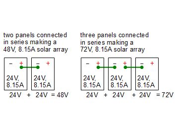
Series strings.
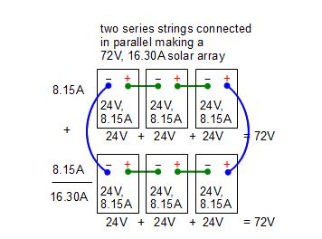
Parallel.
In the diagram on the right, the values shown in the rectangles that represent individual solar panels are the maximum power voltage and the maximum power current. Your solar array is made up of some number of series strings connected in parallel. These terms were covered when you sized your battery bank but are worth repeating here. Connecting solar panels in series means connecting the positive of one panel to the negative of the next panel, and so on, as shown on the right. A set of panels connected in this way is called a series string, or just a string. When you do this, the voltages of all the panels in the string are added up to get a larger voltage. The total current is the same as for a single solar panel. So if you need a higher voltage output from your solar array then you'll be connecting more panels together in series. Connecting solar panels in parallel means connecting the positives together and the negatives together. When connecting series strings of panels together, only the positives at one end of the strings are connected together and the negatives at the other end of the strings are connected together. The diagram on the right shows this. When you do this, the total current is equal to the current for one solar panel multiplied by the number of strings that are connected together. The total voltage is the same as for a single series string. |
Our example
We start out with the watt hours needed per day from the working out your power needs page, 2922 Wh/day. The suggested voltage to start with is 24 volts. In our area I happen to know we get an average of 3 hours of sunshine per day on a year round basis. Shopping around, I found a solar panel whose Maximum Power Current is 8.15 amps and whose Maximum Power Voltage is 28 volts. So my starting values are:

Entering the above in the calculator and clicking on the Calculate button tells us that the solar array voltage will be 35V and that the current on the wires from the solar array will be 50.94amps. We then go to the voltage drop calculator and enter the following parameters:

The voltage drop calculator tells us that for 50.94amps we will require a wire size of 2 gauge (AWG), which is much too expensive. So we go back to the above solar array calculator and increase the Solar array volage to 72 V, entering the following parameters:

As a result of that we are told that the solar array voltage will be 105 V and that the current on the wires from the solar array will be 20.38 amps. Going back to the voltage drop calculator and with the new voltage and current we enter this:

This time the voltage drop calculator tells us the wire needs to be 8 gauge (AWG) which is more affordable.
So the result is that we need of 6 solar panels. We'll wire them as 2 series strings with 3 panels in each string. Then we'll connect the 2 strings in parallel. This is the same as the parallel example in the above diagram. Also, the wire between the solar array and the charge controller will be 2 40 foot lengths of 8 AWG insulated wire, one for the positive and one for the negative. We'll of course either need to run a ground wire, also 8 AWG, or hammer a ground rod into the ground at the array.
Some items to consider
At this point there are some items you need to look at that may cause you to change the above values.
Item 1. Is the current on the wires from the solar array too high?
One of the last values calculated and shown near the bottom above is the current that will be on the wires going from the solar array to the charge controller. This is usually two or more very long wires, maybe going from the roof to the basement or from the base of a pole, then underground in conduit and then into the basement. The higher the value you get for this, the thicker that wire will have to be. And copper wire is expensive so you want it to be as thin as possible.
You can get some idea of how thick this wire will need to be by using this wire sizing/voltage drop calculator.
Once you know the thickness of wire you can shop around. If the price is too much then redo the above calculation starting with a higher Solar array voltage. If you went through the above example, you'll see that we did just that.
Item 2. The current on the wires from the solar array must be at least 2% the battery bank capacity
As with item 1 above, this involves the current that will be on the wires going from the solar array to the charge controller. A battery just sitting idle will lose 2% of its charge per day. Your solar panels must therefore provide enough current to keep it topped up. In other words, the current coming from your solar panel must be at least 2% of your battery bank's capacitiy. In Step 2, the battery sizing calculator, you calculated your battery bank's capacity. To help you make sure that the solar array you came up with above provides at least 2% of the needed current, the size of a battery bank that your solar array's current is 2% of is given as one of the outputs of the calculator above. If that value is larger than your battery bank capacity then you're okay. If not, then you'll have to start the form above with a larger Watt hours needed per day until the battery bank capacity calculated above is larger than your battery bank capacity. Most often this isn't an issue.
Item 3. Your charge controller must handle an extra 25% amps
A lake, snow and clouds all reflect extra sunlight onto your solar array. It's as if there are extra suns in the sky. As a rule of thumb we add an extra 25% to the current that will be on the wires going from the solar array to the charge controller. This becomes the amount of current that your charge controller will need to be able to handle as input and is a value to consider when shopping for your solar panel. The value for this has been calculated at the bottom of the above calculator.
The end result for step 3
You now know which solar panels you'll need, how many and how you'll configure them (series/parallel). In figuring that out you've probably already figured out what size wire you'll need between your solar array and the charge controller. Click on an icon at the top or bottom of this page to go to another step.
