DIY Solar Pool Heating in Tuscany
The following is a very complete article about a DIY solar pool
heating system located in Tuscany, Italy. It was designed and
put together by Ken Gordon, from Scotland. Any inquiries can
be made to Ken at
 .
Many thanks for his writing up this excellent report and making it
available to everyone.
.
Many thanks for his writing up this excellent report and making it
available to everyone.
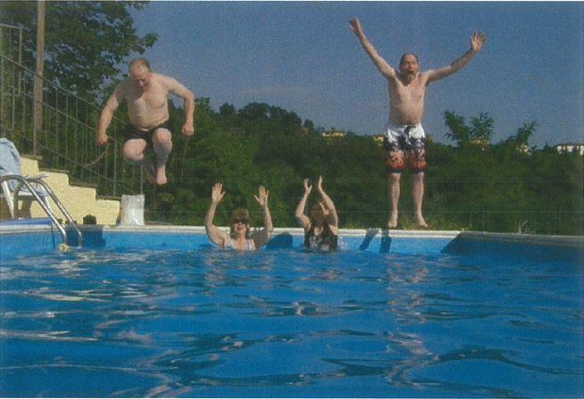
Results (taken from emails)
The result was an outstanding success; water temperature when we arrived was 19°C on 1st June. It took two days to install the collectors, and today our friends have reported back that the pool is now a cosy 28°C and rising - a pleasant improvement! At mid-day today with an ambient temperature of 34°C in the shade the solar gain was a whacking 13.5 kW!
Update - August, 2010
The collectors have been an outstanding success with pool temperatures in the high 20's to low 30's for most of the season - just perfect!
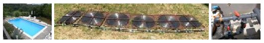
Solar Panel to Heat a Swimming Pool in Barga, Tuscany
1. Introduction
This solar heating system was installed in early June 2010 on a swimming pool in Barga, Northern Tuscany. The solar panels were made from standard regular polyethylene pipe and fittings and mounted onto plywood and timber frames. The total project cost (excluding labour) was in the region of one tenth of a similarly sized commercial system.
The following article describes how the project was designed and assembled.
2. Panel Design
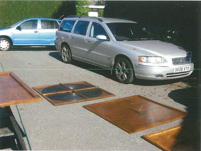
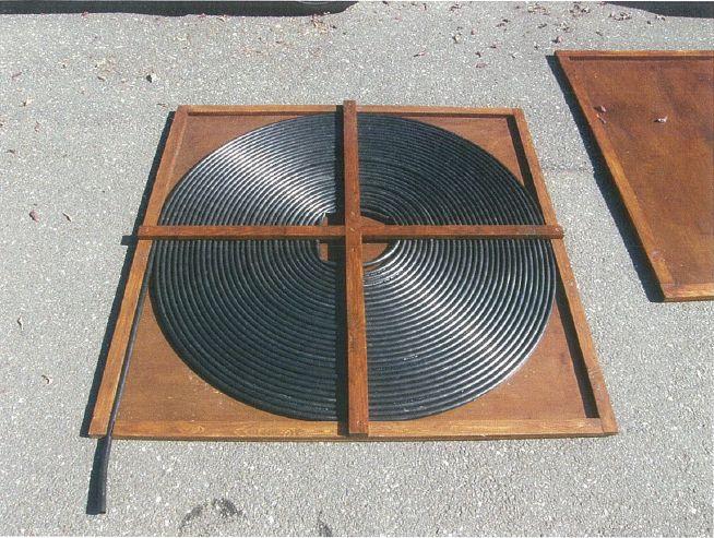
The first step was to design a simple solar panel - using readily available materials. In the UK sheet plywood comes in 8 feet x 4 feet sheets (although this is now metricated to 2.4m x 1.2m). To keep the panel light enough to transport 5mm thick plywood was used. The sheet was cut into two equal parts each providing a 4ft x 4ft square. The square was given rigidity by pinning (nailing) and gluing a frame around the edge of each square. The frame was made of dressed (smooth) pinewood timber 1½" x ¾" (40mm x 20mm). (See photo 2).
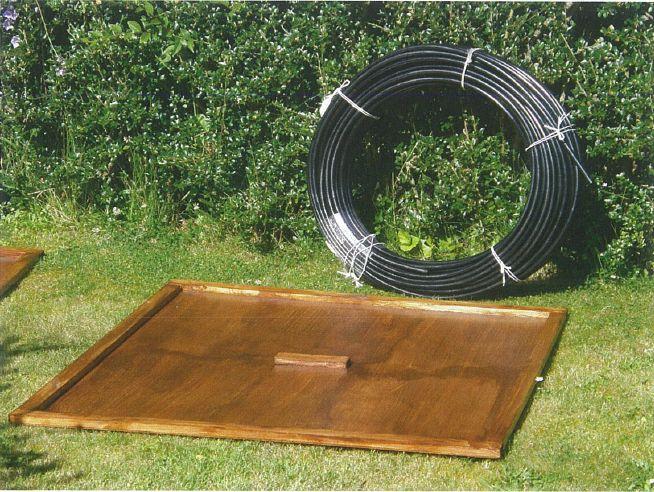
The frame gave a basic support for the pipe which was coiled into the centre in a spiral (like a Katherine wheel). The 4ft x 4ft sheet accepted approximately 60m of pipe.
The pipe selected was 16mm (½") low density polyethylene, black in colour. The pipe was held in place on the board by pinning and gluing a cross-piece over the pipework in the frame. This was achieved again using 40mm x 20mm dressed timber which was cut to form two interlocking "housing" joints (see photo 4) at the centre. A short length of 40mm x 20mm timber was pinned and glued to the centre of the board to give support and strength. The board and cross piece was made separately and then stained a dark colour to protect the timber and to help absorb the heat. Matt black paint could also have been used. Once fully coated (I used 3 coats) and dry, the pipe was coiled onto the frame and finally the cross-piece glued and pinned in place. This was perhaps the most difficult part which requires at least two people to hold the pipe in place until the cross-piece can be secured.
The first panel completed, we carried out some trials to gauge its performance. Luckily for us it was an unusually warm day in the North of Scotland and by early afternoon the temperature had reached 19°C in the shade.
We ran cold water through the panel at a flowrate of 8.7 litres/min (6.9 secs to fill a one litre container). The water temperature entering the panel was 14.1°C and leaving was 15.4°C, giving us a 1.3°C temperature rise and much inspiration.
Knowing the flowrate, and temperature rise we were now in a position to calculate the heat gain (or power) of the panel.
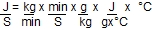
The formula is
Q = M x S x

where
Q = Heat (Joules)
M = Mass of water (grams)
S = Specific heat of Water (4.186 J/g°C)
= Temperature change (Temperature out minus temperature in)
But this only gives the heat transfer for a panel field with sitting water; when the panel is in use the water is constantly being replaced as it flows through, so we get
Qs (= Q/second) = Ms (M per second) x S x
where
Qs = Heat per second = Power (Watts)
Ms = Mass of water flowing per second
S = Specific Heat of Water (4.186 J/g°C)
= Temperature change (°C)
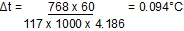
So for our panel we have
Ms = 8.7 lit/min = 8.7kg/min = 0.145kg/sec
S = 4.186 J/g°C
= 1.3°C
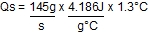
= 789 J/s
= 789 Watts
= 0.789 kW
Therefore each panel can potentially generate 0.789 kW of power, even in Northern Scotland! The next step is to estimate how much power is required to heat the pool. It was decided to simplify this calculation by ignoring heat losses from the water at night. This could be measured at a later date, and if a pool cover was required, one would be purchased.
Ed. The above tests show that these DIY solar collectors are around 80% efficient, the same as with manufactured flat rubber panel collectors. The reasoning is as follows. The outer diameter of the round spiral panel is 4ft, which is 1.2 meters, making the radius 0.6 meters. The area of a circle is pi x radius squared, so the panel is 3.14 x 0.6 x 0.6 = 1.13 square meters, a little more than 1 square meter. At sea level, the amount of sunlight is 1000 watts per square meter. That means that when he made the measurement the collector was receiving around 1000 watts from the sun while putting out only 789 watts. Therefore the efficiency is 789 watts / 1000 watts = 78.9%.
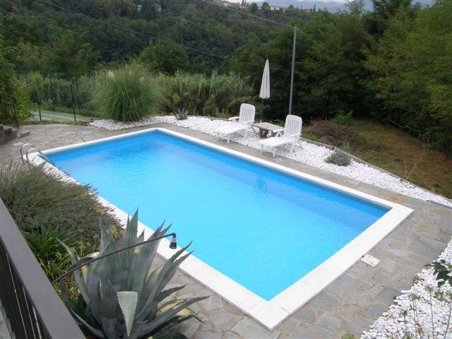
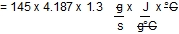
The pool dimensions were 8m x 4m with a water depth of 1.4m, giving a total water volume of 8 x 4 x 1.4 = 44.8m3. The pump installed on the pool was a STA-RITE 5PZRC1. The operating pressure of the pump was 1.0 bar (10m) during normal recirculation through the sand filter. By referring to the pump curve (Figure 1) it is shown that the flowrate at this pressure is just over 7m3/hr (117 lit/min).
This means that for a pool volume of 44.8m3 it will take the pump 44.8/7 = 6.4 hours to turn over the water.
It is generally accepted that a domestic pool should be turned over once every 4 to 6 hours, so the existing pump is operating at its limit.
The pipework connecting to the pool was 1½" (38mm) and it is a generally accepted industry standard that pipe velocity should be 1.5m/s for a flow which is not too low (causing solid particles to settle in the pipes) or too high (causing unnecessary friction loss, noise or pipe wear/erosion). The maximum acceptable velocity is 2.1m/s.
Armed with this knowledge, we had to accept that if we were going to use the existing circulation pump it was necessary to reduce friction loss through the panels to a minimum.
Finally we had to decide how many panels to employ to achieve a sensible 1°C rise in temperature per day. With a heating rate of 0.768kW and a flow rate of 7m3/hr, the same maths is used to calculate this. Knowing that we can put 0.768kW into the water, at a flowrate of 7m3/hr (117 litres/min) we can calculate that the water temperature rise will be as follows:
Qs = Ms x S x
Therefore
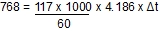
Therefore
It was calculated above that the pool water is re-circulated once every 6.4 hours, so if we assume that this is twice during the period when heat is available, the temperature rise would be 0.094°C x 2 = 0.188°C per panel. We are looking for a temperature rise of at least 1°C/day, so to achieve this we need 6 panels, that is
6 x 0.188 = 1.128°C
The heat output of 6 panels is 0.768 x 6 = 4.608kW which is close to the recommended heater capacity generally accepted as being suitable for a pool of this size.
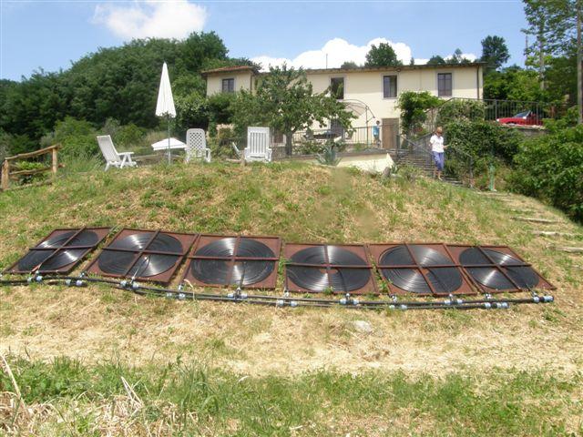
The panels were arranged side-by-side facing due south and tilted at an angle of approximately 45° to the horizontal, to maximise solar gain.
We were lucky that our chosen pool in Tuscany was built on a terrace, with the pool pump and filter located on the next terrace below with a slope between the two laid at 45° and facing due South. A perfect location for our panels.
Ed. Click here for a solar pool heater collector sizing worksheet that you can play around with that was made based on the above formulas.
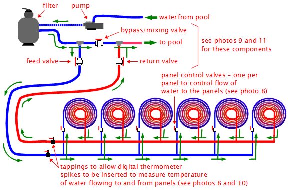
3. System Design
Once we had established that the panels were to be constructed using 16mm MDPE pipe and that there would be 6 panels piped up in a parallel configuration, the rest was reasonably straightforward.
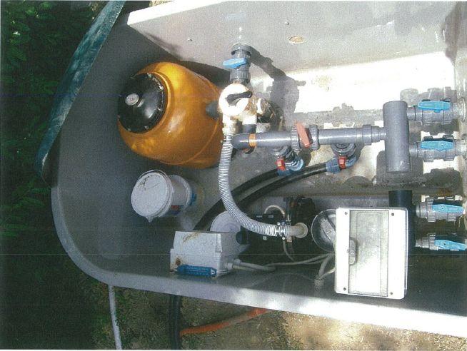
The pipework and fittings were designed to provide minimum friction to ensure that pool circulation would not be compromised. We were lucky in that we were able to site the panels within 15 metres of the pool filter and pump (Photo 5).
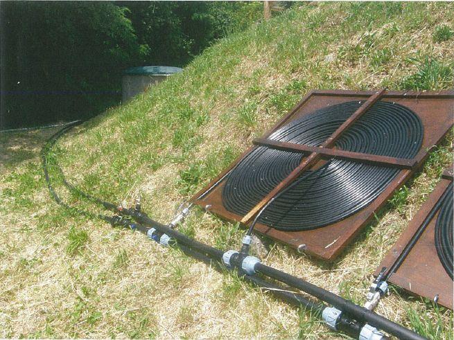
The existing pipework in the pump and filter chamber was 1½", so we decided that to reduce additional pipe friction to a minimum, we would use the same pipe size. The equivalent in MDPE is 50mm (which is an outside diameter, with a nominal inside diameter of 38mm). This was used as a lateral distribution system shown in the photos before installation (photo 6) and after installation (photo 7).
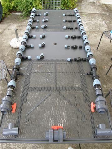

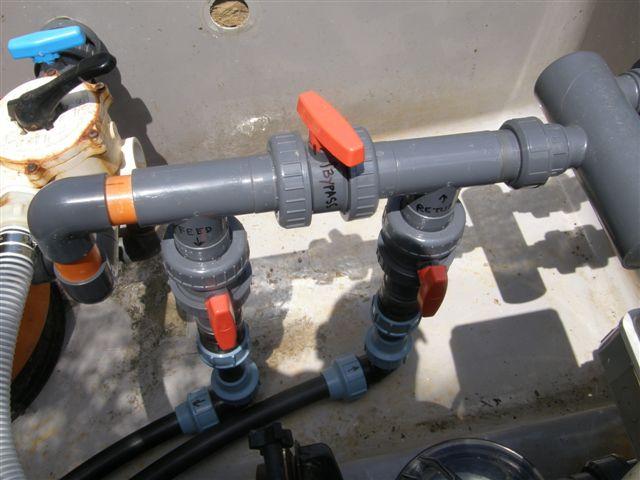
In addition it was decided that it would be necessary to fit the system with valves to allow the solar panels to be switched on and off so that the water could be circulated:
- directly to the pool
- through the solar panels
- directed part to pool and part to panels
This allows complete flexibility. The method of piping this is shown in photo 9.
As this was an experimental installation we also fitted isolation valves to each panel, and a further two small valves so that the temperatures into and out of the panels could be measured (Photo 10 ).
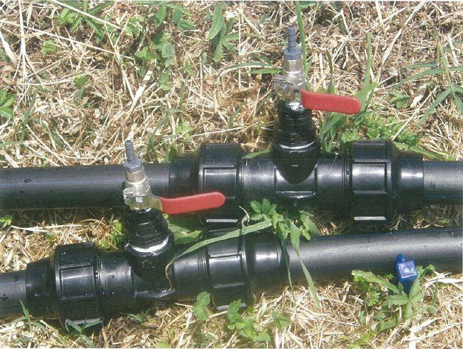
The two valves for measuring temperature were found to be extremely useful in deciding how to run the system for best efficiency, but in the long term may not be required as much.
Figure 2 shows a general system diagram putting the major pieces together in one place as well as showing the water flow. Note that none, some or all of the water can be made to flow through the bypass valve (see the two sections starting here for more on controlling flow, pressure and temperature using three valves.)
4. Results in Operation
The results were outstanding; raising the pool water temperature from 19°C on 1st June to 29°C by 14th June.
This amounts to a temperature increase of 10°C in 14 days which equates to 0.714 °C/day. This is slightly lower than the theoretical figure of 1.28°C as the rise took place in early summer and no pool cover was used, so losses would be expected.
5. Conclusion
The panels were simple to build, easy to install, low-cost, and proved to be an outstanding success due to the application of good engineering principals.
All parts required to make these low-cost solar panels are readily available. Outdoor swimming in early June in Barga is now a pleasure for all, not just for the Spartans.
Efficiency calculations
Ken's tests above show that these DIY solar collectors are around 80% efficient, the same as with manufactured flat rubber panel collectors. This is calculated from Ken's test above where he gets 789 watts from a single panel (see section 2. Panel Design.) The outer diameter of the round spiral panel is 4ft, which is 1.2 meters, making the radius 0.6 meters. The area of a circle is pi x radius squared, so his panel was 3.14 x 0.6 x 0.6 = 1.13 square meters, a little more than 1 square meter. At sea level, the amount of sunlight is 1000 watts per square meter. That means Ken's collector when he made the measurement was receiving around 1000 watts from the sun while putting out only 789 watts. Therefore the efficiency is 789 watts / 1000 watts = 78.9%.
This made it possible to do sizing of these systems using calculators from commercial solar pool heating vendor's websites. See this page on sizing a DIY solar system for more on this. Thanks to Gary at builditsolar.com for pointing this out.
|
Do you have a project you'd like to share on rimstar.org too? You're more than welcome to. Click here for details. |
|

