Ball bearing motor
The ball bearing motor is a strange looking motor that doesn't seem to have any motor. In the photo below, all you see is a wooden disk mounted on a metal shaft which is mounted on two ball bearings. But you also see that there are electrical connections to the bearings! And that's a clue to where the motor lies. The bearings are the motor. These work with both alternating current (AC) and direct current (DC). In both cases, a low voltage, high current is used.
The real mystery is in how it works. No one is sure. All we have are theories, one of which is given below.
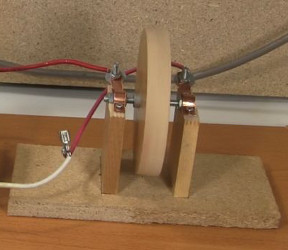
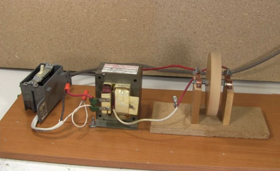
In the photos below are how the electrical connections are made for this one. Copper strips are bend over the bearings, holding them in place. Wires from the power supply are connected to the copper strips. This means electricity flows to the metal bearings through these copper strips.
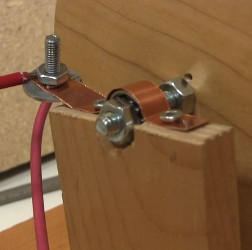
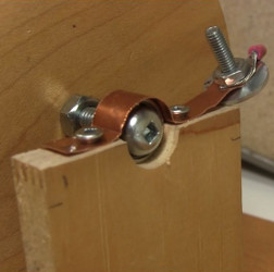
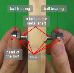
As shown below in green, the path the electricity takes is through the wires from the power supply, through the copper strips, through the bearings, and across the metal shaft from bearing to bearing. As you can see above, the metal shaft is just a bolt with nuts on it to hold everything in place.
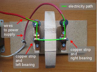
WARNING The above photos show the ball bearing motor being run from a microwave oven transformer that's getting its input from the wall socket. In the above photo you can see that all three coils are still on the transformer, including the very dangerous high voltage, high current coil with the many turns of thin wire. It's not in used but it is energized.
If you use one of these transformers, remove that coil first. Or better yet, use the output from a soldering iron with the tip removed instead. One wire going to the motor would be connected to the soldering iron's output and the other wire would be connected to Earth ground. Another alternative is to use a battery like a car battery, while taking the necessary precautions as these too can be dangerous.
How a ball bearing motor works
It's not known for sure how these work, but the following is one popular theory.
Thermal expansion of the bearings
As the first diagram below shows, there is a high electrical current from the copper strip, through the outer race (the rings are called races), through the balls, to the inner race and to the shaft (not shown.)
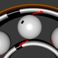
The second diagram shows that the ohmic resistance where the balls meet the races causes those areas to heat up and bulges a minute amount. But as the third diagram shows, these bulges would just push against the races and cause the balls to seize up and stay put.
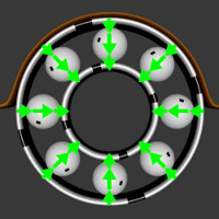

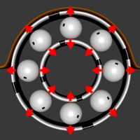
However, if you first give the flywheel a turn, which starts the balls and races turning, then as the diagram below shows, the bulges would develop slightly offset, and would push on the races causing the whole thing to accelerate and keep turning.
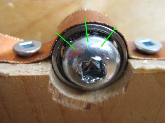
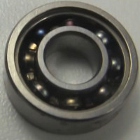
The problem with this heating is that if it's too much then the metal of the bearing can carbonize, and at that point the motor will still turn easily by hand but the effect you not longer work. The photo below shows a bearing that still turns freely but will not work in a ball bearing motor.
Video - Ball Bearing Motor - How to Make/How it Works
This video shows how I made the above ball bearing motor, shows it in action and gives the animated version of the thermal expansion explanation for how it works.
