Gyroscopes made with vinyl records
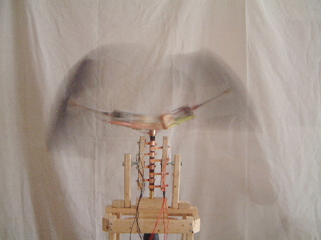
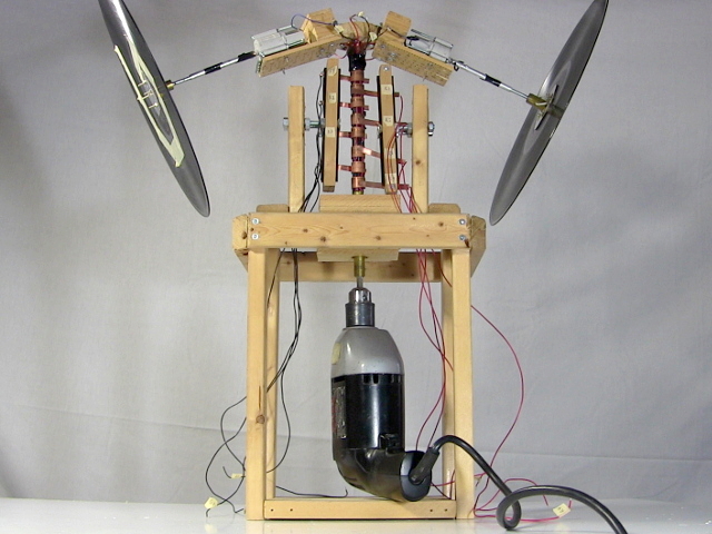
Just for fun I made a large set of motorized gyroscopes that demonstrate gyroscopic precession. The disks are made using vinyl records. It's hard to tell but in the first photo below, not only are the two disks spinning but the whole 'T' shaped section is spinning. There's a fun video below of them in action.
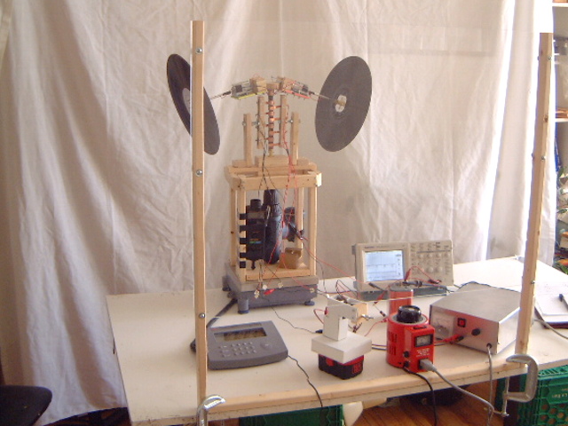
Another part of the reason for doing it was to demonstrate that there is no weight loss when the disks rise up while spinning. That's the case even when the gyroscopes are prevented from rising by fixing them in place horizontally. You can see the gyroscopes sitting on a digital scale in the photo above (I also used a phototachometer to measure the rotational speed of the two together). Of course I got zero weight change when I did so, even though placing a single playing card on the wooden frame would cause a weight change.
How the gyroscopes are made
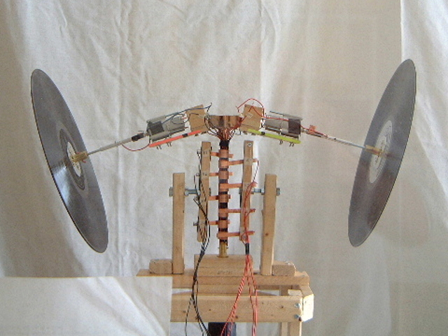
Each gyroscope consists of a small DC motor with a vinyl record connected to its shaft (see the photos below).
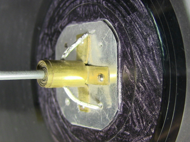
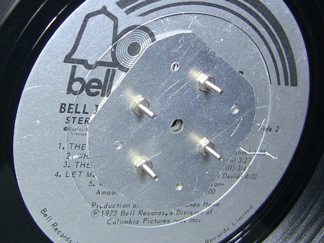
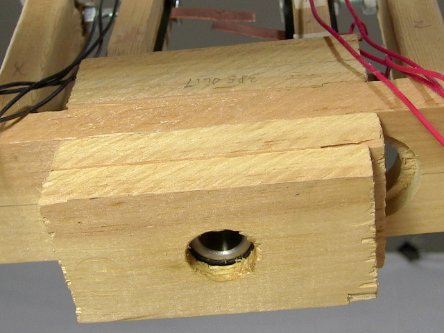
Each vinyl disk is attached to a motor shaft using something made of a bunch of brass tubes inside each other to go from the small diameter of the motor shaft to a large diameter that can handle the resulting torque better. A hole is then drilled all the way through all the tubes and the motor shaft and a stiff wire (the white clothes hanger wire in the photo below) is put through the hole to keep it all in place. The wire is then bent into a 'C' shape so that it can't fall out. The outermost brass tube has part of it bent outward 90 degrees where it's bolted onto the vinyl disk. How you connect to the vinyl disk will depend on what's available to you -- this is just one approach of many.
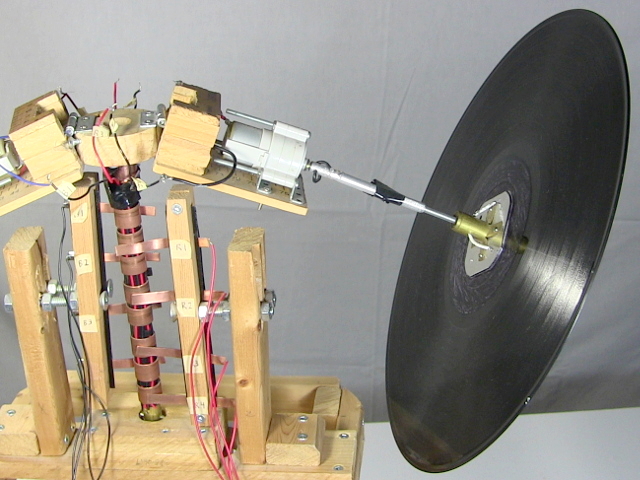
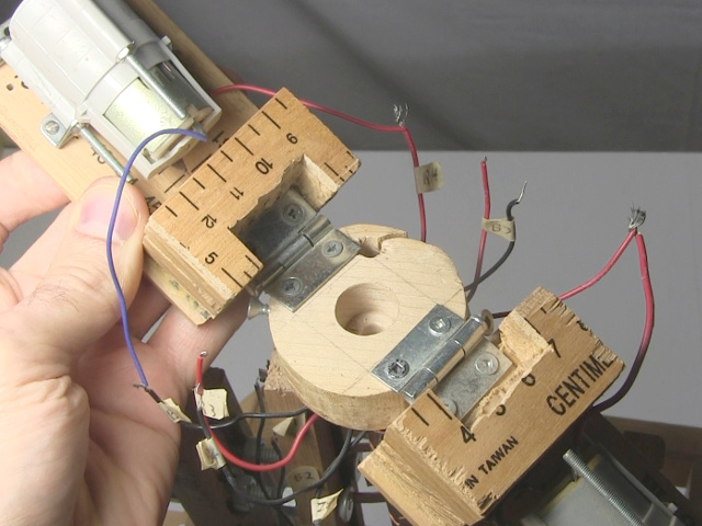
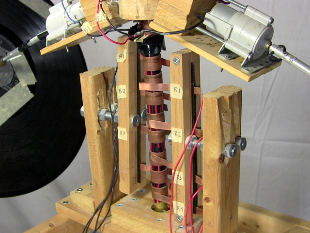
To get the gyroscopic precession to happen I also need to rotate each motor and gyroscope. To do that they are both attached to a vertical shaft as if they formed the top of the letter 'T'. That vertical shaft is turned using a drill.
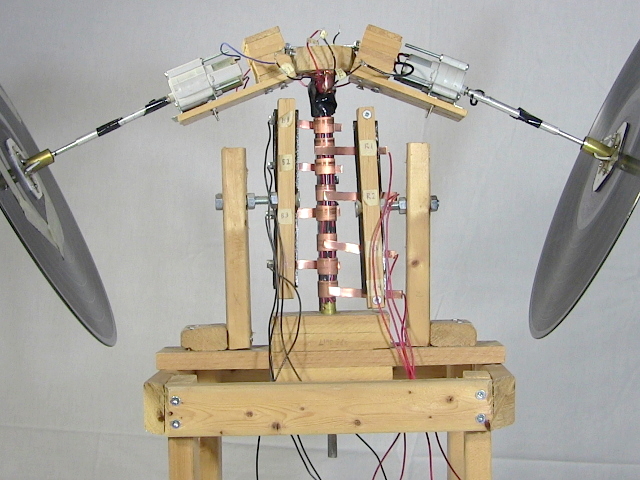
To allow each gyroscope to angle upward when everything is spinning, the two gyroscopes are connected to the vertical shaft using hinges.
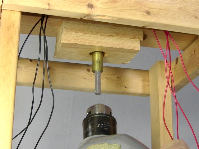
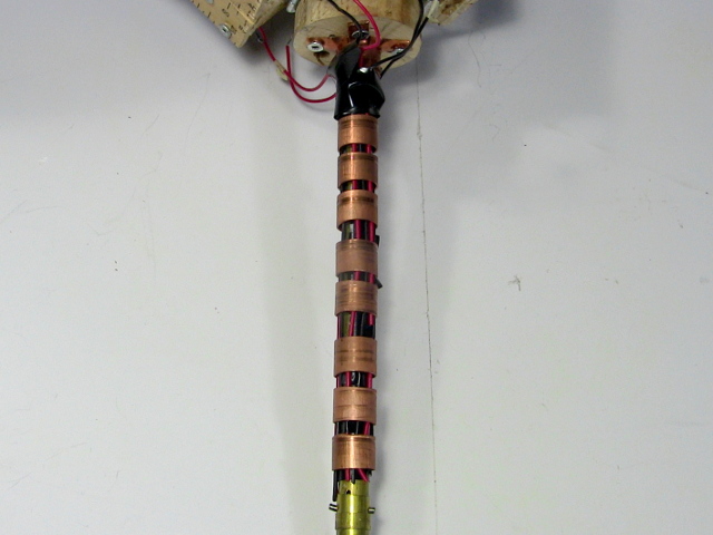
The vertical shaft is made up of a wooden dowel for most of it that's then attached by a homemade coupler made of brass tubes to a shorter metal shaft that the drill grips onto. The wooden dowel is completely covered by other parts in the photo below. It could all have been one piece instead if I had either a long enough metal rod, or a smaller diameter wooden dowel that would fit in the drill.
That vertical shaft is held vertical by two bearings. The bearings are housed in homemade wooden blocks.

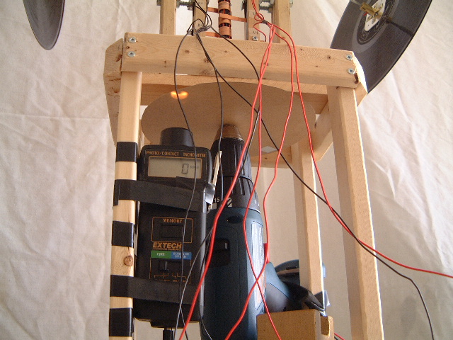
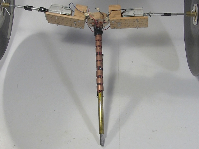
If I had batteries that were both powerful enough to power the gyro motors and that were also small then I would have mounted them in the same area as each gyro motor. But I didn't and so instead I powered them using either bigger batteries or a DC power on the table (see the photo of the gyroscopes on a digital scale above). To transfer the power from the tabletop to the spinning motors I made some DIY/homemade slip rings or commutators (photos below).
I ran wires up to copper strips which are held in a support structure that makes their positions adjustable. As said above, the vertical shaft at that point is a wooden dowel, but I cut short lengths of copper pipe to make copper rings. On the inside of each copper ring I soldered one wire. I then spaced these copper rings apart on the shaft with all the wires inside and running up to the motors.
The shaft is then put in place such that each copper strip lines up with one copper ring. The reuslts is that each wire going to a copper strip is always electrically connected to the wire that's connected to whichever copper ring the strip touches, even when the shaft is spinning. This is called a slip ring or a commuator. And that's how wires coming from things on the table connect to the motors.
Note that I really needed only four slip rings to power the motors, two for each motor (positive and negative). I made eight because I'd tried a method of measuring the rotational speed of the gyroscopes that didn't work. So only four are needed.
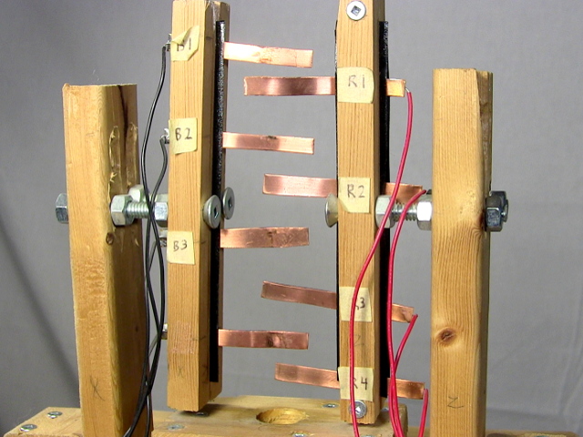
All the complicated mechanism you see above for holding the copper strips in place is just to make it easy to adjust their positions. That's probably all overkill, and can probably be done simpler.
Video - Gyroscope Precession Demonstrations and Flying Saucer Fun
In the following video I walk though the whole thing a little and demstronstrate it in action. I also talk about a fun flying saucer thing I saw in a magazine article when I was young and didn't know much about physics yet. It's something that doesn't work but is fun to think about.
