3-wheeled autonomous robot
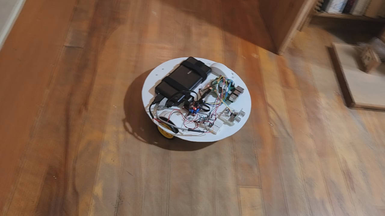
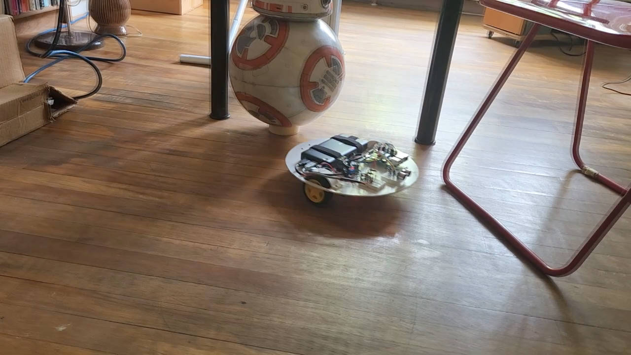
Here's how to make a 3-wheeled robot, it can even be an autonomous robot like this one.
Autonomous robot
The robot is autonomous, it can wander around on its own for a long period of time until it runs into a situation that it can't handle. Here's how...
- The US-100 ultrasonic sensor is used to detect if there is anything within 30cm/1 foot in front of it. If it does detect anything then it stops and rotates clockwise for a short period of time. It then checks again if there's anything in front of it. If there isn't then it continues moving straight, otherwise it rotates and looks again.
- The HC-020K motor encoder speed sensors are used to measure if both wheels are not rotating. If they're not then they may have run into an obstacle and are stuck. In that case, just like with the ultrasonic sensor, it stops and rotates clockwise for a short period of time. It then checks again if there's anything in front of it. If there isn't then it continues moving straight, otherwise it rotates and looks again.
Other simple enhancements may be to turn in random directions and to try backing up.
Video - How to Make 3-Wheeled Automonous Robot
Here's the video showing the robot in action (at the beginning and end of the video) but mostly all the steps in building it, including the mistakes and their solutions.
The design
In case you want to download the 3D model that I created and make modifications of your own, here's where to get it. You can download Blender for free from https://www.blender.org/. The model was created using Blender 3.20.
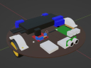
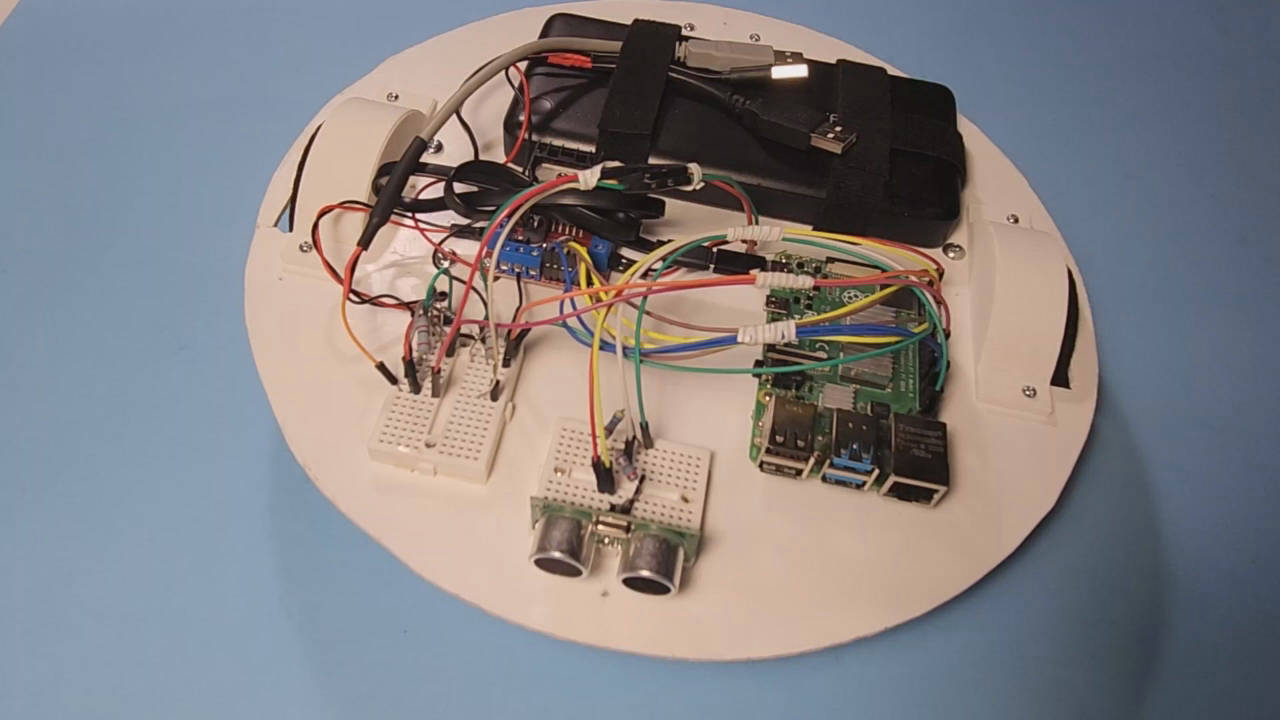
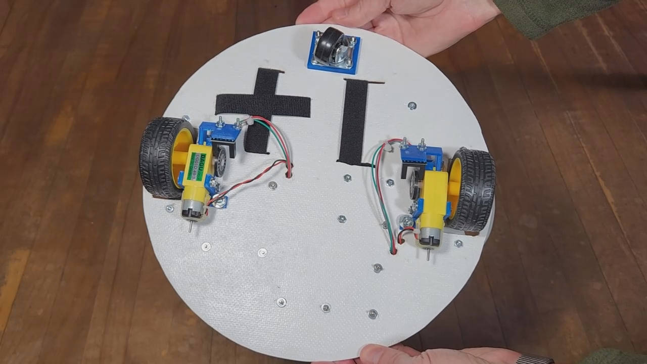
The parts
The parts are:
- 2 TT DC motors
- 1 caster wheel
- RAVPOWER cell phone battery charger
- L298N motor controller board
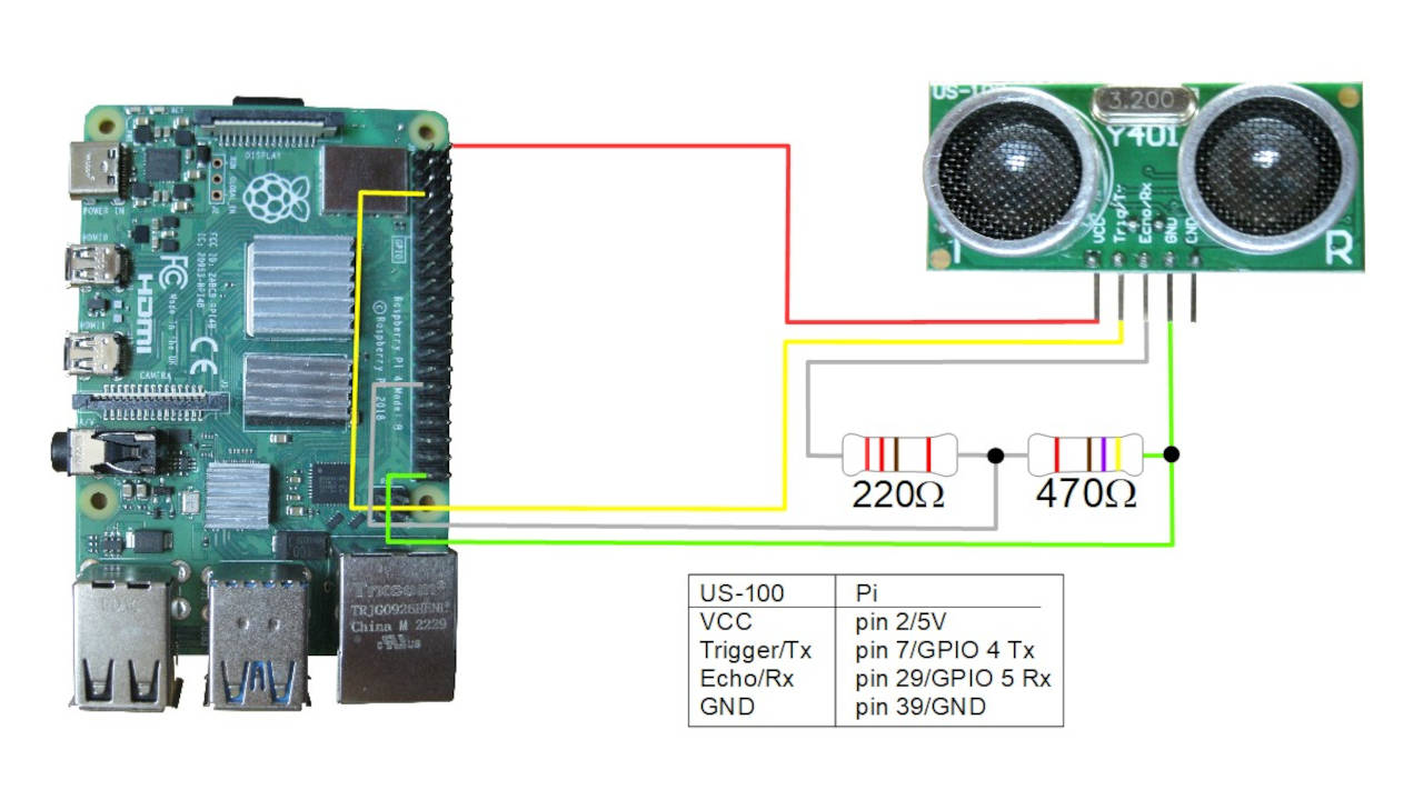
- US-100 ultrasonic sensor for detecting obstacles
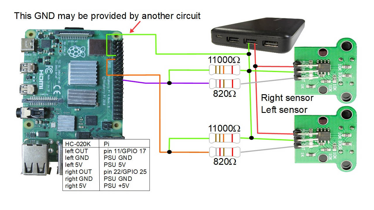
- 2 HC-020K motor encoder speed sensors for measuring the motor speed and detecting when it's stopped (perhaps because it got stuck)
- Raspberry Pi 4B
- 2 small breadboards
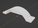
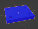
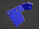
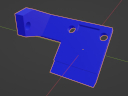
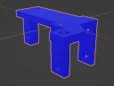
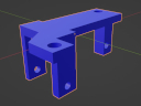
3D printed parts
If you intend to make one like mine then you might want to 3D print some wheel covers. Here are the files in .stl and .blend format (they were created using Blender 3.20.
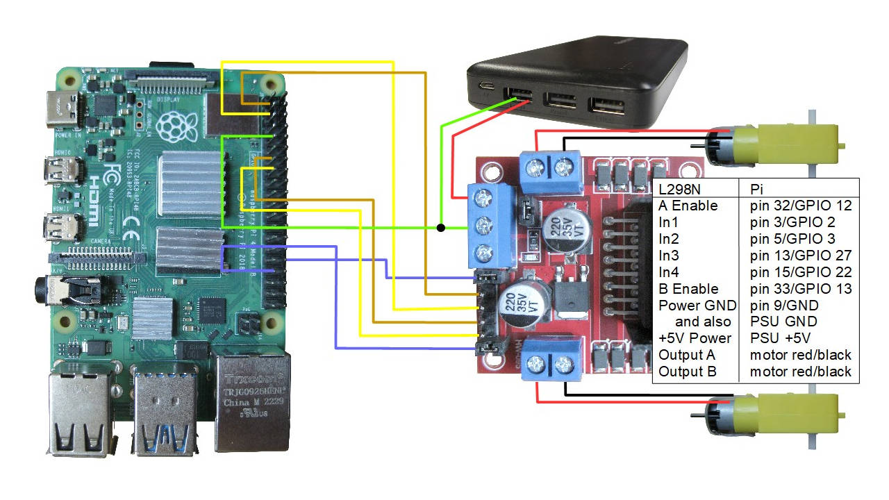
Circuit diagrams
The following are the circuit diagrams used for this robot. Note that you can use any combination of them depending on the features you want the robot to have. The pins used on the Raspberry Pi 4B have been selected so that there is no overlap.
The source code
The following python code examples are some simple test programs for testing the motors, the US-100 ultrasonic sensor, the HC-020K motor encoder speed sensors and then the code for the full autonomous robot.
Simple L298N motor driver python code to test the motor movement
The hardware required is as follows:
- the 2 TT DC motors
- the L298N motor controller
- the battery
- Raspberry Pi 4B
The following python code simply makes the robot move forward for 1 second, turn for 2 seconds, and move forward for 1 second.
import RPi.GPIO as GPIO
from time import sleep

GPIO.setmode(GPIO.BCM)
GPIO.setwarnings(False)

class Motor():
        def __init__(self, Ena, In1, In2):
                self.Ena = Ena
                self.In1 = In1
                self.In2 = In2
                GPIO.setup(self.Ena, GPIO.OUT)
                GPIO.setup(self.In1, GPIO.OUT)
                GPIO.setup(self.In2, GPIO.OUT)
                self.pwm = GPIO.PWM(Ena, 100)
                self.pwm.start(0)

        def moveF(self, x=50, t=0):
                GPIO.output(self.In1, GPIO.LOW)
                GPIO.output(self.In2, GPIO.HIGH)
                self.pwm.ChangeDutyCycle(x)
                sleep(t)

        def moveB(self, x=50, t=0):
                GPIO.output(self.In1, GPIO.HIGH)
                GPIO.output(self.In2, GPIO.LOW)
                self.pwm.ChangeDutyCycle(x)
                sleep(t)

        def stop(self, t=0):
                self.pwm.ChangeDutyCycle(0)
                sleep(t)

motor1 = Motor(12, 2, 3)
motor2 = Motor(13, 27, 22)

# From looking at it from the top with the Pi being the front:
# motor1 is the right side, motor2 is the left side

sleep(1)
motor1.moveF(50, 0)
motor2.moveF(60, 0)
sleep(1)
motor1.moveB(50, 0)
motor2.moveF(60, 0)
sleep(2)
motor1.moveF(50, 0)
motor2.moveF(60, 0)
sleep(1)
motor1.stop(0)
motor2.stop(0)
#motor1.moveB(30, 0)
#motor2.moveB(30, 0)
#sleep(5)
#motor1.stop(0)
#motor2.stop(0)
Simple US-100 ultrasonic sensor python code
The hardware required is as follows:
- a US-100 ultrasonic sensor
- the 2 TT DC motors
- the L298N motor controller
- the battery
- Raspberry Pi 4B
The following python code simply loops, getting distance measurements from the US-100 sensor and printing the distances. See the comments in the code.
"""
test_us100_uart.py - Test program to read from US-100 ultrasonic
sensor in UART mode on Raspberry Pi. This was tested on a Raspberry Pi 4B.

To put it in UART mode, if you're using the US-100 then put the jumper in
place on the US-100 board. Then on the Pi, edit /boot/firmware/config.txt:

$ sudo vi /boot/firmware/config.txt

and add something like the following three lines for the desired UART to
the bottom of the file (this example uses uart3):

# enable serial interface
enable_uart=1
dtoverlay=uart3

Reboot the Pi and /dev/ttyAMA3 will now exist. On the Raspberry Pi 4B,
UART3 is GPIO pins 4 and 5.

Note that I'm no python expert so this can probably be written better.

The idea is that you write 0x55 to the serial port and then read back
two bytes. To turn the two bytes into a distance in millimeters,
multiply the most significant byte by 256 and add on the least significant
byte.

"""

import serial
import time

ser = serial.Serial("/dev/ttyAMA3", 9600)

while True:

    nbytes = ser.write(b'\x55')
    distance = ser.read(size=2)
    distlist = list(distance)
    finaldist = (distlist[0]*256 + distlist[1]) / 10.0
    print('Distance is %.1fcm' % finaldist)

    #time.sleep(2)
Simple HC-020K motor encoder speed sensor python code
The hardware required is as follows:
- the 2 HC-020K motor encoder speed sensors
- the 2 TT DC motors
- the L298N motor controller
- the battery
- Raspberry Pi 4B
The following python code simply makes the robot move around in various ways while an interrupt callback for the motor sensors prints out the GPIO pin, the rpm, the time and the duration (the time between holes in the encoder wheel).
# Pointers for how to handle the Python interrupts came from here:
# https://roboticsbackend.com/raspberry-pi-gpio-interrupts-tutorial/
#
# Originally I was getting:
# RuntimeError: Failed to add edge detection
# for the lines:
# GPIO.add_event_detect(hcleft.pin, GPIO.RISING,
#         callback=hc020k_left_interrupt_callback)
# From searching online, all sources told me to:
# sudo apt remove python3-rpi.gpio
# sudo apt install python3-rpi.lgpio
# That fixed it immediately.

import signal
import sys
import RPi.GPIO as GPIO
import time
from time import sleep

HC020K_LEFT_PIN = 17
HC020K_RIGHT_PIN = 25

def SIGINT_signal_handler(signal, frame):
    GPIO.cleanup()
    sys.exit(0)

class Motor():
        def __init__(self, Ena, In1, In2):
                self.Ena = Ena
                self.In1 = In1
                self.In2 = In2
                GPIO.setup(self.Ena, GPIO.OUT)
                GPIO.setup(self.In1, GPIO.OUT)
                GPIO.setup(self.In2, GPIO.OUT)
                self.pwm = GPIO.PWM(Ena, 100)
                self.pwm.start(0)

        def moveF(self, x=50, t=0):
                GPIO.output(self.In1, GPIO.LOW)
                GPIO.output(self.In2, GPIO.HIGH)
                self.pwm.ChangeDutyCycle(x)
                sleep(t)

        def moveB(self, x=50, t=0):
                GPIO.output(self.In1, GPIO.HIGH)
                GPIO.output(self.In2, GPIO.LOW)
                self.pwm.ChangeDutyCycle(x)
                sleep(t)

        def stop(self, t=0):
                self.pwm.ChangeDutyCycle(0)
                sleep(t)

class HC020K():
    def __init__(self, pin):
        self.pin = pin
        self.nholes = 20
        self.lasttime = 0
        self.rpm = 0;
        GPIO.setup(self.pin, GPIO.IN)

    def interrupt_callback(self):
        now = time.time()
        if self.lasttime != 0:
            duration = now - self.lasttime
            # duration * self.rpm: how long a rotation takes in seconds  based
            #                       on time the between the last two holes
            # 1 / (duration * self.time): gives rotations per second
            # Multiply that by 60 seconds / minutes give rpm.
            # Which is: 60 * 1 / (duration * self.time)
            self.rpm = 60 / (duration * self.nholes)
            print("pin %d" % self.pin)
            print(" rpm = %f" % self.rpm)
            print(" now = %f" % now)
            print(" duration = %f" % duration)
        self.lasttime = now

def hc020k_left_interrupt_callback(channel):
    hcleft.interrupt_callback()

def hc020k_right_interrupt_callback(channel):
    hcright.interrupt_callback()

GPIO.setmode(GPIO.BCM)
#GPIO.setwarnings(False)

hcleft = HC020K(HC020K_LEFT_PIN)
hcright = HC020K(HC020K_RIGHT_PIN)

# The bouncetimes are needed because on the oscilloscope, I could see that
# each rising edge was noisy, consisting of really multiple short spikes,
# resulting in multiple rising edges. Similarly for the falling edges.
# These spikes needed to be ignored and that's what the bouncetime parameter
# in milliseconds is for.
#
# The time between consecutive rise and rise on the oscilloscope assuming
# no spikes was usually around 20 to 22, with a time of each rise and fall
# to around 8 milliseconds, again ignoring spikes. So a bouncetime of
# around 10 seems good for ignoring all the noise to get only the time
# from one rise to the next rise, ignoring all the spikes. This gave
# durations of around 20, matching the oscilloscope output.

GPIO.add_event_detect(hcleft.pin, GPIO.RISING,
        callback=hc020k_left_interrupt_callback, bouncetime=10)
GPIO.add_event_detect(hcright.pin, GPIO.RISING,
        callback=hc020k_right_interrupt_callback, bouncetime=10)

signal.signal(signal.SIGINT, SIGINT_signal_handler)

motor1 = Motor(12, 2, 3)
motor2 = Motor(13, 27, 22)

#signal.pause()

# From looking at it from the top with the Pi being the front:
# motor1 is the right side, motor2 is the left side

sleep(1)
motor1.moveF(50, 0)
motor2.moveF(60, 0)
sleep(1)
motor1.moveB(50, 0)
motor2.moveF(60, 0)
sleep(2)
motor1.moveF(50, 0)
motor2.moveF(60, 0)
sleep(1)
motor1.stop(0)
motor2.stop(0)
Full autonomous robot code
The hardware required is as follows (all the hardware for this robot):
- a US-100 ultrasonic sensor
- the 2 HC-020K motor encoder speed sensors
- the 2 TT DC motors
- the L298N motor controller
- the battery
- Raspberry Pi 4B
The following python code is the full autonomous robot code that avoids obstacles using the US-100 ultrasonic sensor and also detects and uses the HC-020K motor encoder speed sensors to handle when the wheels are stuck.
# Pointers for how to handle the Python interrupts came from here:
# https://roboticsbackend.com/raspberry-pi-gpio-interrupts-tutorial/
#
# Originally I was getting:
# RuntimeError: Failed to add edge detection
# for the lines:
# GPIO.add_event_detect(hcleft.pin, GPIO.RISING,
#         callback=hc020k_left_interrupt_callback)
# From searching online, all sources told me to:
# sudo apt remove python3-rpi.gpio
# sudo apt install python3-rpi.lgpio
# That fixed it immediately.

import serial
import signal
import sys
import RPi.GPIO as GPIO
import time
from time import sleep

HC020K_LEFT_PIN = 17
HC020K_RIGHT_PIN = 25

# this is the time during which if we don't see another motor encoder hole
# then we assume the motor is stopped
STOPPED_TIME = 0.3
# this is the time for rotating to a new viewpoint to look again
ROTATE_TIME = 2

def SIGINT_signal_handler(signal, frame):
    GPIO.cleanup()
    sys.exit(0)

class Motor():
        def __init__(self, Ena, In1, In2):
                self.Ena = Ena
                self.In1 = In1
                self.In2 = In2
                GPIO.setup(self.Ena, GPIO.OUT)
                GPIO.setup(self.In1, GPIO.OUT)
                GPIO.setup(self.In2, GPIO.OUT)
                self.pwm = GPIO.PWM(Ena, 100)
                self.pwm.start(0)

        def moveB(self, x=50, t=0):
                GPIO.output(self.In1, GPIO.LOW)
                GPIO.output(self.In2, GPIO.HIGH)
                self.pwm.ChangeDutyCycle(x)
                sleep(t)

        def moveF(self, x=50, t=0):
                GPIO.output(self.In1, GPIO.HIGH)
                GPIO.output(self.In2, GPIO.LOW)
                self.pwm.ChangeDutyCycle(x)
                sleep(t)

        def stop(self, t=0):
                self.pwm.ChangeDutyCycle(0)
                sleep(t)

class HC020K():
    def __init__(self, pin):
        self.pin = pin
        self.nholes = 20
        self.lasttime = 0
        self.rpm = 0;
        GPIO.setup(self.pin, GPIO.IN)

    def interrupt_callback(self):
        now = time.time()
        if self.lasttime != 0:
            duration = now - self.lasttime
            # duration * self.rpm: how long a rotation takes in seconds  based
            #                       on time the between the last two holes
            # 1 / (duration * self.time): gives rotations per second
            # Multiply that by 60 seconds / minutes give rpm.
            # Which is: 60 * 1 / (duration * self.time)
            self.rpm = 60 / (duration * self.nholes)
            print("pin " + str(self.pin) + " rpm = " + str(round(self.rpm, 1)) + " now = " + str(now) + " duration = " + str(round(duration, 4)))
        self.lasttime = now

def hc020k_left_interrupt_callback(channel):
    hcleft.interrupt_callback()

def hc020k_right_interrupt_callback(channel):
    hcright.interrupt_callback()

def stop_and_wait_for_stop():
    motorr.stop(0)
    motorl.stop(0)
    while True:
        now = time.time();
        if (now - hcright.lasttime > STOPPED_TIME) and \
           (now - hcleft.lasttime > STOPPED_TIME):
            # assume both motors have stopped
            print("Both motors are probably stopped after stopping deliberately")
            break


GPIO.setmode(GPIO.BCM)
#GPIO.setwarnings(False)

hcleft = HC020K(HC020K_LEFT_PIN)
hcright = HC020K(HC020K_RIGHT_PIN)

# The bouncetimes are needed because on the oscilloscope, I could see that
# each rising edge was noisy, consisting of really multiple short spikes,
# resulting in multiple rising edges. Similarly for the falling edges.
# These spikes needed to be ignored and that's what the bouncetime parameter
# in milliseconds is for.
#
# The time between consecutive rise and rise on the oscilloscope assuming
# no spikes was usually around 20 to 22, with a time of each rise and fall
# to around 8 milliseconds, again ignoring spikes. So a bouncetime of
# around 10 seems good for ignoring all the noise to get only the time
# from one rise to the next rise, ignoring all the spikes. This gave
# durations of around 20, matching the oscilloscope output.

GPIO.add_event_detect(hcleft.pin, GPIO.RISING,
        callback=hc020k_left_interrupt_callback, bouncetime=10)
GPIO.add_event_detect(hcright.pin, GPIO.RISING,
        callback=hc020k_right_interrupt_callback, bouncetime=10)

signal.signal(signal.SIGINT, SIGINT_signal_handler)

motorr = Motor(12, 2, 3)
motorl = Motor(13, 27, 22)

#signal.pause()

ser = serial.Serial("/dev/ttyAMA3", 9600)

STATE_MOVING_FORWARD_LOOKING = 1
STATE_ROTATING_TO_LOOK_AGAIN = 2
STATE_STOPPED_AND_LOOKING = 3

RIGHT_SPEED = 80
LEFT_SPEED = 80
motorr.moveF(RIGHT_SPEED, 0)
motorl.moveF(LEFT_SPEED, 0)
state = STATE_MOVING_FORWARD_LOOKING
# give it time to accelerate from stopped otherwise we'll just
# loop around and think it's still stopped
#time.sleep(0.05)
accel_start_time = time.time();

while True:

    nbytes = ser.write(b'\x55')
    distance = ser.read(size=2)
    distlist = list(distance)
    finaldist = (distlist[0]*256 + distlist[1]) / 10.0
    now = time.time();
    print("St" + str(state) + " Distance " + str(finaldist) + "cm, motor r = " + str(round(hcright.rpm, 1)) + "rpm, l = " + str(round(hcleft.rpm, 1)) + "rpm" + " now = " + str(now))

    if state == STATE_MOVING_FORWARD_LOOKING or state == STATE_STOPPED_AND_LOOKING:
        if finaldist < 30:
            if state == STATE_MOVING_FORWARD_LOOKING:
                print("stopping, something is in the way, rotating, setting STATE_ROTATING_LOOK_AGAIN")
                stop_and_wait_for_stop()
                # we stopped because something was in the way, rotate
                motorr.moveB(RIGHT_SPEED, 0)
                motorl.moveF(LEFT_SPEED, 0)
                rotate_until = now + ROTATE_TIME # rotate
                state = STATE_ROTATING_TO_LOOK_AGAIN
            elif state == STATE_STOPPED_AND_LOOKING:
                print("stopped, something is in the way, rotating, setting STATE_ROTATING_LOOK_AGAIN")
                # we were stopped and looking and found that something is still
                # in the way, rotate some more
                motorr.moveB(RIGHT_SPEED, 0)
                motorl.moveF(LEFT_SPEED, 0)
                rotate_until = now + ROTATE_TIME # rotate
                state = STATE_ROTATING_TO_LOOK_AGAIN
        else:
            if state == STATE_MOVING_FORWARD_LOOKING:
                # check if either motor is not moving when it should be, i.e., stuck
                if ((now - accel_start_time > 0.5) and \
                    ((now - hcright.lasttime > STOPPED_TIME) and \
                     (now - hcleft.lasttime > STOPPED_TIME))):
                    # assume both motors are stuck
                    print("was moving forward but a motor is probably stuck, trying rotating")
                    stop_and_wait_for_stop()
                    # we stopped because something was in the way, rotate
                    motorr.moveB(RIGHT_SPEED, 0)
                    motorl.moveF(LEFT_SPEED, 0)
                    rotate_until = now + ROTATE_TIME # rotate
                    state = STATE_ROTATING_TO_LOOK_AGAIN
            elif state == STATE_STOPPED_AND_LOOKING:
                print("stopped, nothing in the way, moving forward, setting STATE_MOVING_FORWARD_LOOKING")
                motorr.moveF(RIGHT_SPEED, 0)
                motorl.moveF(LEFT_SPEED, 0)
                state = STATE_MOVING_FORWARD_LOOKING
                # give it time to accelerate from stopped otherwise we'll just
                # loop around and think it's still stopped
                #time.sleep(0.05)
                accel_start_time = time.time();
    elif state == STATE_ROTATING_TO_LOOK_AGAIN:
        if now >= rotate_until:
            print("stopping, setting STATE_STOPPED_AND_LOOKING")
            stop_and_wait_for_stop()
            # we stopped because we finished rotating, look while stopped
            state = STATE_STOPPED_AND_LOOKING
        # else keep rotating

    #time.sleep(2)
    #sleep(1)
